Welcome to Our Community

Some features disabled for guests. Register Today.

Upgrading the “old” C-Beam machine

Discussion in 'CNC Mills/Routers' started by Ronald van Arkel, May 24, 2016.

  1. Ronald van Arkel

    Staff Member Builder Resident Builder

    Joined:
    May 7, 2014
    Messages:
    472
    Likes Received:
    245
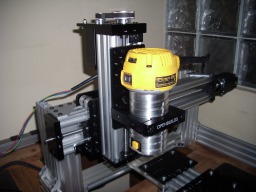
    The DeWalt DW611 won't be used, it will be a DW660 with a cheap motor/fan/router controller from e-Bay to lower RPM to 10,000rpm.


    The DW6600 has the lower plastic cover removed and thus you need a 7/16" and 5/8" wrench to change bits. 3mm spacers are used to reuse the screws that hold the lower part of router/cutting-tool. First idea to make a base for this cutting-tool using the same four screws but as these screws don't go into a metal body I would not recommend it. The cutting-tool has a small stator that is only around 1-1/2" wide (just 38mm) and you want only use clamps in that area! The cutting-tool isn't round so a clamp from Inventables is NOT recommended ( GrabCAD ) ; This clamp will squeeze the four "corners" of the DW660 and not the full plastic body. The area you can use to hold the DW660 in place is the height of the DeWalt sticker, don't clamp under or above of that sticker as it's just a plastic hull and nothing more.


    We used a 4" PVC pipe with a 1/8" wall that we cut to 38mm (1-1/2") in length, and then we cut that "ring" again so we could squeeze it into the DW611/Bosch Colt router base. The result are good, no play at all at the tip of the bit!


    The good thing is, the DW660 comes with a 1/8" collet! The shaft is also longer thus it might be more suitable for 3D carving. It's less than half the price compared to a Bosch Colt (1HP) or DW611 AND it can be shipped to Mexico. Now, how about that, DeWalt tools for America are made in Mexico but they are not sold in Mexico and the DW611 can't officially be imported for personal use (the DW660 can!). The Bosch is sold here for 180-200USD so naa (1/4" collet stock), we'll better get the DW660 for our builds here.


    Here is a picture how it turned out:

    IMG_0100549.JPG

    -Ronald
     
    Mark Carew and GrayUK like this.
  2. Quas7

    Quas7 New
    Builder

    Joined:
    Sep 19, 2017
    Messages:
    8
    Likes Received:
    0
    Hi everybody,

    I am a complete newby to CNC and I only have gained some experience with building a few 3D printers (coreXY, Prusa,...). I am definetly much more experienced with electronics than with mechanics.

    I got my first C-beam router ordered form OB and one of it's uses will be fine pitch PCB engraving, i.e. <0.5mm features. (And yes, there will be HEPA filter system for the glass fibre dust, etc.)

    Therefore, I just wanted to know, if those belt upgrades for higher torque do not reduce accuracy and more important repeatability of the machine. Just from the OB actuator tests I see more than a doubling in errors as soon as a belt is involved and this would be too much for fine pitch PCB engraving.
    For me, that makes sense as even for steel core belts the rubber teeth will always add some backlash/hysteresis.
    Is this correct?

    Just for reference: OpenBuilds Actuator Tests V2.pdf

    Best,
    Till
     
  3. Metalguru

    Metalguru Veteran
    Builder

    Joined:
    Dec 29, 2015
    Messages:
    752
    Likes Received:
    548

    Ahhhh, I think there's some confusion here. The C-Beam machine doesn't use belts... it uses lead screws.

    If you are doing engraving with the stock CBM, you might find it difficult to level the table and keep it level to within a few thou needed for fine enraving. That's why I did this build:

    https://openbuilds.com/threads/improved-cbm.10195/

    - to address the floppy table issues on the original CBM design, and to increase the machinable area. The table is rock steady and adjustable for level to withing a few thou.

    MG


    MG
     
  4. Quas7

    Quas7 New
    Builder

    Joined:
    Sep 19, 2017
    Messages:
    8
    Likes Received:
    0
    Thany you MG for your input!
    The wheeled linear rails from your linked mod are a very promising straight forward concept. I will implement it.

    I already selected the OB C-beam router for its ACME screws to get the inital resolution and repeatability.
    I just was curious, if belts would have been able to get close enough to lead screw performance to mill fine pitch PCBs. I guess, this is not the case.

    My initial approach for leveling would have been building a little plastic vacuum chuck for the pcb fixation and flattening positioning it right in the middle of the bed for maximum support.
    By firstly milling the whole surface of this chuck with the CNC, this should be as parallel to the head movement as it could get.
    The rest of height error I would have compensated in software (smoothieware) as it is done with leveling sensors for 3D printing but with a conductive Z-probe in this case.
    Looks like no open source vacuum chucks are on OB, yet. Maybe, I will make this my first posted build.

    Best,
    Till
     
  5. Rick 2.0

    Rick 2.0 OpenBuilds Team
    Staff Member Moderator Builder Resident Builder

    Joined:
    Dec 20, 2013
    Messages:
    2,892
    Likes Received:
    1,551
    Every rotation of the stepper moves a screw drive system 8mm. Every rotation of a GT3 belt drive system moves 60mm. You would need a fairly substantial geared reduction stepper to get a belted system even close to screws. For such a lightly loaded system, you could drop down to GT2 belts which would 40mm per turn but you can see there is still a significant difference.
     
    Quas7 likes this.

Share This Page

  1. This site uses cookies to help personalise content, tailor your experience and to keep you logged in if you register.
    By continuing to use this site, you are consenting to our use of cookies.
    Dismiss Notice