Welcome to Our Community

Some features disabled for guests. Register Today.

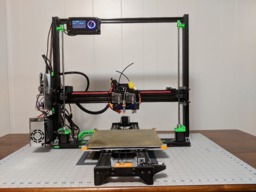
BinaryConstruct V3

Discussion in '3D printers' started by BinaryConstruct, Feb 28, 2018.

  1. BinaryConstruct

    Builder

    Joined:
    Apr 28, 2014
    Messages:
    19
    Likes Received:
    28
    BinaryConstruct published a new build:

    Read more about this build...

    Fusion 360 Assembly: A360
     
    #1 BinaryConstruct, Feb 28, 2018
    Last edited: Mar 1, 2018
  2. BinaryConstruct

    Builder

    Joined:
    Apr 28, 2014
    Messages:
    19
    Likes Received:
    28
    I am still uploading my drawings and parts. Fusion 360 is giving my some headaches sharing the project files. I will upload STLs once I have them exported.
     
  3. Anthony Bolgar

    Anthony Bolgar Journeyman
    Builder

    Joined:
    Jan 14, 2016
    Messages:
    354
    Likes Received:
    198
    I like the design. I have a question about the frame top rail, would it not be better to use a 20X40 extrusion just like the sides?
     
  4. BinaryConstruct

    Builder

    Joined:
    Apr 28, 2014
    Messages:
    19
    Likes Received:
    28
    The single 20x20 offset to the rear allows you to slide the t-nuts down the frame for the Z motor bracket and the lead screw supports. This makes assembly a lot easier than trying to hit a t-nut behind a printed part on a vertical structure, since you can pre-assemble the parts with t-nuts on them.
     
  5. JustinTime

    JustinTime Veteran
    Builder

    Joined:
    Dec 18, 2013
    Messages:
    784
    Likes Received:
    259
    Did you print the green parts on a different printer than the black parts? I'm asking since I'm straggling with banding on my prints and I see that the black parts have the same banding as I have it but on the green parts I don't see it. I know the banding has something to do with the z-axis screws but I can't seem to solve the problem.
     
  6. BinaryConstruct

    Builder

    Joined:
    Apr 28, 2014
    Messages:
    19
    Likes Received:
    28
    The banding was due to some earlier designs of this printer used a hanging z lead screw. Once I flipped it and secured the top with thrust bearing as tight as possible, the banding went away.

    In my case I am using the spiral cut aluminum motor mount. They were expanding and contracting like a spring causing z layers a different thicknesses.

    Yes I did use a different printer, but now the issue is solved.
    Nearly all of the parts for this printer we're printed by itself. In the interim, I used temporary aluminum extrusions for parts like the y end caps and open builds part store motor brackets or wood blocks.
    This was I was able to get a working printer with 0 printed parts, and gradually print improvements. The secured leadscrew and better belts have been the biggest quality improvements so far.
     
  7. pek

    pek Journeyman
    Builder

    Joined:
    Apr 17, 2017
    Messages:
    196
    Likes Received:
    130
    Very interesting build, thanks for sharing. How heavy is the X axis? Does the Z axis with gantries works well?
     
  8. BinaryConstruct

    Builder

    Joined:
    Apr 28, 2014
    Messages:
    19
    Likes Received:
    28
    It is fairly heavy, due to the mass of the dual extruders and motors. I am running my z motors wired in series to compensate.

    This eliminated a step skipping issue I had when the z motors we're wired in parallel. The banding issue was partially caused by unsecured leadscrew and partial by missed steps.

    Currently I print with no problems at 120mm/s with PLA as long as I lay down the first layer at 30-40mm/s.
    Some early versions had horizontal banding that was caused by a belt that was too stiff. I was experimenting with "zero" stretch belts, and they conducted too much vibration, especially at high speed. The slightly stretchy belts have a damping effect.
     
    Anthony Bolgar likes this.
  9. OtterZA

    OtterZA New
    Builder

    Joined:
    Jul 30, 2018
    Messages:
    1
    Likes Received:
    0
    I like your design for it's rigidity and simplicity. How did you align the Y with the X-Z frame?
     
  10. BinaryConstruct

    Builder

    Joined:
    Apr 28, 2014
    Messages:
    19
    Likes Received:
    28
    Very careful measurements with a square. It actually wasn't too hard, just requires a little patience and a few test prints. You can measure diagonals on test prints to figure out if you are out of alignment.
     

Share This Page

  1. This site uses cookies to help personalise content, tailor your experience and to keep you logged in if you register.
    By continuing to use this site, you are consenting to our use of cookies.
    Dismiss Notice