Welcome to Our Community

Some features disabled for guests. Register Today.

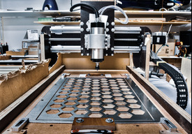
Gantry Style CNC from plywood

Discussion in 'CNC Mills/Routers' started by C-CNC, Nov 1, 2018.

  1. C-CNC

    C-CNC New
    Builder

    Joined:
    Oct 30, 2018
    Messages:
    19
    Likes Received:
    9
    C-CNC published a new build:

    Read more about this build...
     
  2. GeoffH

    GeoffH Journeyman
    Builder

    Joined:
    Mar 11, 2017
    Messages:
    178
    Likes Received:
    107
    Making a CNC Router from very thin plywood is a big challenge for you. You will need to produce stiff box sections, and use a good quality glue. There are a few Plywood CNC builds on this site but using much thicker, hardwood Plywood. I guess the CNC size will be small?
    Anyway good luck with your project.
     
    C-CNC likes this.
  3. C-CNC

    C-CNC New
    Builder

    Joined:
    Oct 30, 2018
    Messages:
    19
    Likes Received:
    9
    oh got the size wrong. 2.4cm... I also added the size in the summary...
     
  4. GeoffH

    GeoffH Journeyman
    Builder

    Joined:
    Mar 11, 2017
    Messages:
    178
    Likes Received:
    107
    That's good. The model that you have attached seems to be incomplete, I'm guessing that the gantry is not cantilevered?
     
    C-CNC likes this.
  5. C-CNC

    C-CNC New
    Builder

    Joined:
    Oct 30, 2018
    Messages:
    19
    Likes Received:
    9
    No it isn't cantileverd... To save time I only created one side... The model is also just a rough model to get the idea how i want to do it.
     
  6. C-CNC

    C-CNC New
    Builder

    Joined:
    Oct 30, 2018
    Messages:
    19
    Likes Received:
    9
    Could anyone suggest a spindle that quietly still powerful but costs less than 150 €/$ ?
    Im currently thinking about a 400w 48volt spindle with an ER11 colltet for 86€ / 97,74USD. I thought its enough for the start and it could cut aluminum at low speeds.
    By the way, yesterday I tested the x-axis and achieved an feedrate of about 400mm/min (thats around 16"/min) with acceptable torque.
     
    stargeezer likes this.
  7. Rick 2.0

    Rick 2.0 OpenBuilds Team
    Staff Member Moderator Builder Resident Builder

    Joined:
    Dec 20, 2013
    Messages:
    2,899
    Likes Received:
    1,556
    I would suggest using a braced rail. While you'll have plenty of stiffness in the 2.4cm plywood, the rod rails you have shown won't offer much and will be the weakness in your system.

    rail.jpg
     
    C-CNC likes this.
  8. C-CNC

    C-CNC New
    Builder

    Joined:
    Oct 30, 2018
    Messages:
    19
    Likes Received:
    9
    Yes, the model is a bit outdated... im using for the x-axis SBR25 Rails(one for each side) and for the y and z axis SBR20 Rails
    I will post the fusion360 CAD model of the x-axis soon. But i got a lot to do for school right now...
     
  9. stargeezer

    stargeezer Journeyman
    Builder

    Joined:
    Feb 20, 2015
    Messages:
    328
    Likes Received:
    117
    The 400 watt spindle will be a great starting point for your router as long as you are satisfied with it's abilities. Limit your cutter diameter to no bigger than 1/4 inch ( or 6mm) and you will be fine. There is a ton of import 1/8" Cutters on ebay that are very cheap and sharp enough for starting out. When you decide to start cutting aluminum you will need better quality bits, but my son cut up to 1/4" aluminum with a 400w spindle motor and very cheap carbide bits. Just limit your speeds an feeds to what the setup you build can handle with good results. 400 m/minute might be a good rate on wood with one cutter but it might be a disaster when cutting aluminum.
     
    C-CNC likes this.
  10. C-CNC

    C-CNC New
    Builder

    Joined:
    Oct 30, 2018
    Messages:
    19
    Likes Received:
    9
    I just found a brushless 500 watt, 48 volt, ER16 motor and thought brushed motors make a lot of noise ...
    The price is 128USD / 112 €, so 20 USD / 30 € higher. (yes USD to EUR = 1.15 to 1 but ebay dosnt think like that...)
    It's a higher price, but less noise and bigger collets...
    I am not shure if it would be a huge difference so what do you think ?
    (I know it's from cheapo china but I don't have that much money and chinese stuff isn't always that bad : {48V CNC 500W Luftkühl Spindel Motor Brushless + 52mm Clamp + Speed Governor ER16 | eBay} i added the cost of the powersupply in my calculation.)
     
  11. Rob Taylor

    Rob Taylor Master
    Builder

    Joined:
    Dec 15, 2013
    Messages:
    1,470
    Likes Received:
    753
    You'll almost certainly get better results by relying on design rather than material properties on this one. Use thinner plywood for the moving parts, more like 10-15mm rather than 25mm-class stuff, and make sure all of it is in torsion box sections; the base, the columns, the gantry bridge, everything. The thinner wood will save a lot of non-useful weight, whilst the design will add significantly more rigidity than you would have gotten with the thicker material. You could also screw on some cheap aluminum angle on the edges to add some extra stiffness and rail mounting surfaces.

    Use a high performance glue that will also add significant structural support to the whole thing whilst keeping weight down- and can be spread in very thin sections to keep joints from floating too much and won't flow out under screw tension. Not 100% sure what that would be, off-hand, (polyurethane could be a good option?) but there are likely more options in Germany than a lot of other places anyway for those high performance materials.

    At some point, put blasting sand or pool filter sand inside the torsion box sections to help with damping (plywood is fairly resonant for a composite wood product- look at DIY audio applications and musical instrument bodies!). If your axis motors can handle the weight of it, put some in the gantry and carriage too. Adding the MDF for the spoilboard will help there, it's quite damping too.

    Consider your options for not using wood for the gantry carriage/z-axis body; it may be too small a volume to practically use wood. To create a stiff enough structure, you may end up creating too large an overhang, creating a significant moment on your gantry axis mechanicals. It's such a small area that you could probably just use laminated aluminum square tube or something along those lines and get a similar rigidity to plywood in 1/3 the volume, or something. On the other hand, maybe a simple slab of 24mm plywood would be sufficient to do everything because it's so short. Maybe you could use 5mm plywood with the right structure and keep it all shrunk down flat. There are a few possible options, and you can't really know unless you a) try them, or b) run some calculations. Just something that jumps out to me to be aware of though.

    That spindle actually looks pretty decent for what you're doing. 500W, if that's close to actual usable power out and not just marketing, is plenty for basically any material that a plywood machine is gonna cut. Brushless is almost certainly going to be higher power density, likely smoother running and quieter, more usable torque, all that good stuff. I'd keep poking around a little more to see if you can find a 240V EU model, but it may just be the 110V US models that can be found in the lower ~$100-150 range. For cutting wood, you'll definitely appreciate the larger collet options.

    Gearing down your steppers between 2:1 and 4:1 will improve both absolute torque and acceleration (at the cost of top speed rapids) for smoother interpolation and contouring, so maybe consider how feasible it would be to do pulley plates and motor standoffs instead of direct mounting if you're intending on doing a lot of arcs, circles and organic forms vs simple plate-making.
     
    C-CNC likes this.
  12. C-CNC

    C-CNC New
    Builder

    Joined:
    Oct 30, 2018
    Messages:
    19
    Likes Received:
    9
    Im currently running my motors at 800steps per rev (1/4 microstep) that has no reason just thought it could be good.
    The threaded rod got a pitch of 2mm/rev (0.078 inch per rev = 12.7 revs per inch)
    The motor is running at 3.33 revs/sec = 6.66mm/sec = 400mm/min or 15.7inch/min
    Wouldn't it be better to turn down the revs / sec so increasing the torque of the motor instead of gearing it down?
    Thats what I think, but I'm not a professional, so correct me if I'm wrong.
     
  13. C-CNC

    C-CNC New
    Builder

    Joined:
    Oct 30, 2018
    Messages:
    19
    Likes Received:
    9
    I only used this wood cause these plates were meant to be used to be shipping boxes at my dads work, but they never used them so my dad said i could use them..
     
    Rick 2.0 likes this.
  14. Rick 2.0

    Rick 2.0 OpenBuilds Team
    Staff Member Moderator Builder Resident Builder

    Joined:
    Dec 20, 2013
    Messages:
    2,899
    Likes Received:
    1,556
    Build looks great so far. Excellent work. :thumbsup:
    .
     
    C-CNC likes this.
  15. C-CNC

    C-CNC New
    Builder

    Joined:
    Oct 30, 2018
    Messages:
    19
    Likes Received:
    9
    For a 14year old or an adult o_O:D Thanks anyway !
    I newer thought i would get that much support and feedback :thumbsup:
     
  16. GrayUK

    GrayUK Openbuilds Team Elder
    Staff Member Moderator Builder

    Joined:
    May 5, 2014
    Messages:
    1,668
    Likes Received:
    627
    You just came to the right place for that sort of thing!! :thumbsup:
     
    MaryD and C-CNC like this.
  17. Andreas Bockert

    Andreas Bockert Well-Known
    Builder

    Joined:
    Oct 1, 2017
    Messages:
    142
    Likes Received:
    78
    With 2mm / rev you certainly don't want to step down. The typical openbuild screws are 8mm/rev.

    When picking a spindle you'll want something that goes low in the RPMs. Especially if you can't get to run faster than 400mm/min. Ideally, when running 10k RPM you'll want to go about 3000mm/min to get a decent chip. At 10k RPM and 400mm/min you'll be rubbing the bit and generating a lot of toasty dust and burning your carbide...

    What drivers are you using? If you add a fan to them you can get pretty far with DRV8825 drivers. I ran my machine at 4000mm/min with DRV8825 drivers. With 1/8 micro stepping you should be able to hit roughly 2000mm/min before the GRBL/Arduino is maxed out.

    So, add a fan, max your currents and see how high you can push things...

    Maybe I missed it, but do you have a plan for tackling backlash?

    (Btw, in the description you still state that it's 2.4mm plywood, not cm).
     
    C-CNC likes this.
  18. C-CNC

    C-CNC New
    Builder

    Joined:
    Oct 30, 2018
    Messages:
    19
    Likes Received:
    9
    I put the drivers into the description. The drivers can handle up to 4A and 4.5 Amps peak.
    Im using universal GCode sender to controll the Arduino.
    When I tested the motors with a helical drilling operation the motors got really warm. After 25-30 minutes they warmed up to about 50-60°C(125-140°F) so I had to stop the operation and let the motors cool down. I do not know if attaching heatsinks can solve the problem.
    I ran them with 2 Amps so at the rated current -> I won't be able to add more current to increase the torque without frying them.
     
  19. Andreas Bockert

    Andreas Bockert Well-Known
    Builder

    Joined:
    Oct 1, 2017
    Messages:
    142
    Likes Received:
    78
    60C should be within operating range. I think that steppers are ok even at 90-100C.
     
    C-CNC likes this.
  20. stargeezer

    stargeezer Journeyman
    Builder

    Joined:
    Feb 20, 2015
    Messages:
    328
    Likes Received:
    117
    First of all I am with you on every cost saving step you have taken and applaud your efforts to build what you need while finding alternative materials that might have ended with filling up more landfills. You are proving that spending loads of money is NOT required to build a CNC. Great Job!!

    One place I'd urge you to re-examine is your stepper mount. The photo on the Build page shows a gap between your mount and the face of the stepper motor flange. I think that you need to either put a spacer between the motor flange and the mount, cut open the mounts inner bearing space open to clear clear it to give you a flat mount or use washers to fill the gap on each bolt you use. My thoughs are that mounting like you show puts lots of stress one the stepper motor flange that may cause it to part off. The biggest issue is that I doubt those bolts can ever be tightened enough as you show them.

    Just some thoughts you did'nt ask for.

    Larry
     
    C-CNC likes this.
  21. C-CNC

    C-CNC New
    Builder

    Joined:
    Oct 30, 2018
    Messages:
    19
    Likes Received:
    9
    I already disassembled all the parts on the steppermount that were meant to reduce vibrations. I will use some washers to release the stress on the stepper motor

    Thanks for the great thoughts !
     
    stargeezer likes this.
  22. Rob Atha

    Rob Atha New
    Builder

    Joined:
    Aug 19, 2018
    Messages:
    53
    Likes Received:
    7
    I made my first cnc this year, used 18mm ply throughout and it’s a pretty solid build. I’ve looked into using x-frame rails but the cost for some pieces are extortionate and to be honest don’t look rigid enough for what I need.

    I’ve used both my Mikita trimming router but have now opted for a cheap Chinese spindle to cut down on nose and vibration, and it worked well. Although people have mentioned sbr20/25 rails, I opted for sbr12, I believe unless you are mating a monster of a machine, anything larger that this would be overkill.

    91052F11-CFEF-4504-B582-8D28FB1C6BAB.jpeg

    These are just some cuts I’ve managed to achieve with my machine for some Christmas lanterns I’m making and with the setup I’ve used I think they turned out really well considering I’ve only spent £150 to make the machine
     
    MaryD, C-CNC and GrayUK like this.
  23. Rob Taylor

    Rob Taylor Master
    Builder

    Joined:
    Dec 15, 2013
    Messages:
    1,470
    Likes Received:
    753
    Some roughness as you'd expect, but that's super impressive, actually, for 150 quid.

    I think people wildly underestimate how much force a large number of ball bearings spread over multiple planes of a fully supported rail can take. People are out here using 20 and 25mm THK/Hiwin rails when 12mm and sometimes even 9mm rail would be just fine for their machine. It's hard to judge visually when things are engineered like that, common sense has to take a back seat to actual numbers.

    (Also, YORKSHER! :thumbsup:)

    Yes and no. I'd use full or half-stepping on 2mm pitch screws- that's 0.01mm or 0.005mm resolution, respectively- not that you'll actually see that out of the machine, it's just the theoretical output on the nuts themselves. This will also reduce the frequency that your controller has to send at, which is usually a good thing for reliability. As you say, it'll also give you more torque.

    However, gearing achieves more than purely adding torque, it also balances the power transfer between the moving carriage and the motor rotor- you don't want them to get too far away from each other in terms of momentum, or you end up forcing the motor to do a lot of work that you don't actually see out of the machine. Remember, every time you decelerate the carriage, you're basically trying to force its kinetic energy back into the motor... Which the motor doesn't like very much. Gearing helps even the two parts out so it can speed up and slow down much more quickly and efficiently (which it's doing a lot any time you're cutting curves!). On your machine, it might be overkill, but just thought I'd mention it anyway, since inch-thick plywood could be a lot for the motors you're using.
     
    C-CNC likes this.
  24. C-CNC

    C-CNC New
    Builder

    Joined:
    Oct 30, 2018
    Messages:
    19
    Likes Received:
    9
    1 - I now settled on a Nema 23 4.2Amp 435oz-in(3Nm) steppermotor for the y-axis, to get more speed and torque. For the wiring of these I decided to use 4-core 0.75mm² (18-19 AWG) wire (below) which is sufficiently thick for 2 or 4 amps with low voltage drop.
    3 - Is it important for a brushless spindle that the ESC is close ? I know that some brushless motors do but I don't know if this spindle does. I first thought about using the wire mentioned earlier for the spindle but 10amps are way to much for 0.75mm² wire. I could bundle two cores to double the cross-section but I have my doubts about that, because I would need 2 additional cables.
    I would like to hear your opinion about that :)

    1 english:www.Lappkabel.de: Cablefinder
    2 german:www.Lappkabel.de: Kabelfinder
     
  25. C-CNC

    C-CNC New
    Builder

    Joined:
    Oct 30, 2018
    Messages:
    19
    Likes Received:
    9
    I dont know if someone also uses TB6600 stepperdrivers or if it even works with other drivers... Am I able to run a 4amp stepper with only 3 amperes selected on the stepperdrive to get a lower torque ? (to save some power that won't be used)
     
  26. C-CNC

    C-CNC New
    Builder

    Joined:
    Oct 30, 2018
    Messages:
    19
    Likes Received:
    9
    Hey Guys!

    I've got a serious problem with my stepper's. I am currently operating them with TB6600 stepper motor drivers that get are controlled by an Arduino Uno. The Arduino Uno got Grbl installed and is communicating via USB with ugs-platform on my laptop. The steppers are driven at their rated current (2 Amps) but even at no load they are randomly loosing steps. Sometimes they don't loose any but occasionally they even loose steps worth of about 0.2mm (0.008"). Changing the speed or micro-stepping settings didn't really changed something but I found out that at speeds under 100mm/min (4"/min) are the worst and speeds above 1600mm/min (63"/min) doesn't work well either but that is probably because the the steppers aren't build for speeds above 320 rpm.
    I am not sure if it has something to do with the way the Arduino works or if the TB6600 drivers don't work with that system so it would be very cool if you could share your experiences about that topic with me. :)

    By the way I tested everything with an acceleration of 1000 m/s^2 because there was no load and I have tested following microstepping settings:
    -200/rev ( no microstepping)
    -400/rev ( 2*)
    -800/rev (4*)

    Also it would be cool that if you got a similar system and you could share some acceleration/microstepping/feed settings :)

    Thanks!
     
  27. Peter Van Der Walt

    Peter Van Der Walt OpenBuilds Team
    Staff Member Moderator Builder Resident Builder

    Joined:
    Mar 1, 2017
    Messages:
    15,303
    Likes Received:
    4,360
  28. Rob Taylor

    Rob Taylor Master
    Builder

    Joined:
    Dec 15, 2013
    Messages:
    1,470
    Likes Received:
    753
    I think any unreliability is more a product of the variability in packaging and distribution than anything; I've had zero issues with the "Beauty Star" importer versions on Amazon, for instance. And at $11 a piece, you could afford two dead ones out of every three before you start getting into DM542 territory. If they're sufficient for the application (and there isn't a NEMA 17 project they couldn't handle, along with a fair few low/mid-grade NEMA 23 and even some small NEMA 34 projects) the cost efficiency is hard to beat. As with any project, if you need guaranteed functionality the first time out the gate, it's worth paying the extra for, but frequently with electronic projects comprehensive QA and warranties are an expense that may not be worth it.

    There's also the fact that "TB6600" is kind of a genericised term, and what driver IC is actually in there is open to interpretation. I haven't been aware of any where they were severely down-rated to the point that they effectively weren't TB6600-equivalents, though.

    I drive my laser NEMA17s (typical mid-range ones, 50-70oz-in) at 1.2A, I believe 15000mm/s^2 acceleration and 8000-10000mm/min top speed. I always use 8x microstepping because it's the best trade-off between torque and precision.

    Cheaper drivers (and even expensive ones in some circumstances, physics being what it is) may have issues regaining position after a disabling cycle with microstepping, so if you're testing with stops make sure your enable setting is on "always on", it's like $4=256 or something, I forget now.

    Stepper drivers also want specific shapes and timings on their input pulse trains. If, for example, the step pulse duration is near the minimum value, it may sometimes be missed by the driver. Or if there isn't the specified gap between step pulses, or the direction pulse doesn't switch early enough before the next step pulse, etc etc. This shouldn't typically be an issue for Arduino-based controls, but it can come up occasionally.

    It would be very odd for all three/four/whatever drivers to be bad. If all axes are skipping steps, that sounds like a control issue or even a structural issue. If it's just one, make sure it's definitely skipped steps and not lash. This is a wooden machine, remember! Try driving different axes with different drivers, too, see if the problem follows the driver or if it stays on the axis. All the usual troubleshooting steps.

    Double-check that the problem persists with a desktop, too. Likely not an issue with buffered serial commands, but just in case. Laptop I/O can get spotty at precisely the wrong times and often for imperceptibly short durations. Saves battery, not so great for machinery.

    I dunno. Hard to gauge what it might be from just this description, but hopefully it can be fixed without buying a bunch of expensive drivers.
     
  29. C-CNC

    C-CNC New
    Builder

    Joined:
    Oct 30, 2018
    Messages:
    19
    Likes Received:
    9
    @Rob Taylor yeah I also don't like the idea of buying new drivers for another 50 bucks... I found out that at above 1000mm/min at 800 steps per rev the problem disappears and I could achieve a precision of around 0.005mm at a 200mm travel( G01 X100 and G01 X0).

    I have updated all my software and will try out your suggestions I will post the results as soon as I get them and will try to make some video footage.

    Thanks!
     
  30. GeoffH

    GeoffH Journeyman
    Builder

    Joined:
    Mar 11, 2017
    Messages:
    178
    Likes Received:
    107
    Wow, I can't even measure 5 microns. If you can achieve +-0.1mm on your machine you will be doing fine.
     

Share This Page

  1. This site uses cookies to help personalise content, tailor your experience and to keep you logged in if you register.
    By continuing to use this site, you are consenting to our use of cookies.
    Dismiss Notice