Welcome to Our Community

Some features disabled for guests. Register Today.

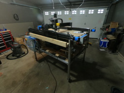
1510 Workbee Modified

Discussion in 'CNC Mills/Routers' started by Jacob Lotter, Dec 2, 2018.

  1. Jacob Lotter

    Jacob Lotter Well-Known
    Builder

    Joined:
    Oct 26, 2018
    Messages:
    34
    Likes Received:
    59
    Jacob Lotter published a new build:

    Read more about this build...
     
    sharmstr likes this.
  2. sharmstr

    sharmstr OpenBuilds Team
    Staff Member Moderator Builder Resident Builder

    Joined:
    Mar 23, 2018
    Messages:
    2,059
    Likes Received:
    1,448
    Awesome! I partially disassembled my 1510 yesterday to deal with the wheels. During that 2 hour time, I told myself I needed to figure out a better solution. This looks like its it! Do you have the cad files? I have a Tormach so machining everything isnt an issue.

    Also, am I correct in thinking that you added the linear rails to the top and bottom of the X gantry, but only to the tops of the Ys?
     
    #2 sharmstr, Dec 2, 2018
    Last edited: Dec 2, 2018
  3. Jacob Lotter

    Jacob Lotter Well-Known
    Builder

    Joined:
    Oct 26, 2018
    Messages:
    34
    Likes Received:
    59
    I actually did this on pen and paper but I can draw something up in a jiffy.

    and Yes only to the top of the y's as I did not see a big point in doing so, as it sees little vertical torque unlike the x axis. Each side has 2 blocks which are spaced on each side of the gantry plate, which isn't seen easily.
     
  4. sharmstr

    sharmstr OpenBuilds Team
    Staff Member Moderator Builder Resident Builder

    Joined:
    Mar 23, 2018
    Messages:
    2,059
    Likes Received:
    1,448
    Great!

    I'm also thinking that if I'm going to do this, I might look into ditching the belts. But it seems like they are working out for you okay.
     
  5. Jacob Lotter

    Jacob Lotter Well-Known
    Builder

    Joined:
    Oct 26, 2018
    Messages:
    34
    Likes Received:
    59
    I will be ditching the belts shortly!! as they are almost as annoying. My plan was to use a normal 10mm or 12mm threaded rod. and make out a low profile nut similar to the ones on the screw machines. Slot one side to take out the backlash and then go nuts. Screw wears down? take out more lash. Screw REALLY wears down? Just buy a new peice of threaded rod. They are pretty cheap anyways. I'll post that when I get it underway in the next coming weeks.
     
  6. sharmstr

    sharmstr OpenBuilds Team
    Staff Member Moderator Builder Resident Builder

    Joined:
    Mar 23, 2018
    Messages:
    2,059
    Likes Received:
    1,448
    That's great news. Looking forward to seeing what you come up with. Let me know if I can help with anything, including the machining.
     
  7. sharmstr

    sharmstr OpenBuilds Team
    Staff Member Moderator Builder Resident Builder

    Joined:
    Mar 23, 2018
    Messages:
    2,059
    Likes Received:
    1,448
    Hey Jacob,

    Why are your through holes and counter bores so big in your drawings?
     
  8. Jacob Lotter

    Jacob Lotter Well-Known
    Builder

    Joined:
    Oct 26, 2018
    Messages:
    34
    Likes Received:
    59
    so big? I made them to side to the stainless socket cap screws (which were a little bigger) that I had with just a bit of slop in case of misalignment. I primarily made this with all metric holes/taps hence why the dimensions seem so odd.
     
    sharmstr likes this.
  9. sharmstr

    sharmstr OpenBuilds Team
    Staff Member Moderator Builder Resident Builder

    Joined:
    Mar 23, 2018
    Messages:
    2,059
    Likes Received:
    1,448
    Got it. The M4 bolts I got were a bit undersize, so going with .200" holes as specified meant over .045" of slop. I ended up drilling .171875 (11/64") holes which worked well. Also had to cut the .625" side down to .600" but probably wouldn't have had to if I stuck with your dimensions :)
     
  10. Jacob Lotter

    Jacob Lotter Well-Known
    Builder

    Joined:
    Oct 26, 2018
    Messages:
    34
    Likes Received:
    59
    hope it works out for you!!! like to see it when you're finished!
     
  11. ken_in_ft_myers

    Builder

    Joined:
    Jun 3, 2018
    Messages:
    1
    Likes Received:
    0
    Have you pick the lead screw diameter yet? If so what size and where are you getting them.I have studied the issue and 12mm looks like they can handle the rpm's I have a 1500mm workbee with 8mm and they whip to much. Will convert to your design. Great work!
     
  12. DA_Spec

    DA_Spec New
    Builder

    Joined:
    May 25, 2016
    Messages:
    14
    Likes Received:
    3
    Nice build ! Does the screw whip ? What speed can you achieve ?
     
  13. Jacob Lotter

    Jacob Lotter Well-Known
    Builder

    Joined:
    Oct 26, 2018
    Messages:
    34
    Likes Received:
    59
    I am currently using 1/2 inch rod and they do whip slightly. Once i get my Control system parts here (ESS, 425oz/in motors, digital steppers) and i can build and install it, I will run some numbers with a dial indicator to see consistency across the machine! Thanks for looking at my build!
     
  14. Jacob Lotter

    Jacob Lotter Well-Known
    Builder

    Joined:
    Oct 26, 2018
    Messages:
    34
    Likes Received:
    59
    The Screw does whip slightly. But not enough to cause concern.. i think hahaha will see in the future! and as speed goes, i will be getting my controls system parts this weekend and will start building it. Might be able to install it and have it running by the new year! Will follow up on everything when completed.
     
  15. matt_o_70

    matt_o_70 New
    Builder

    Joined:
    Dec 15, 2013
    Messages:
    54
    Likes Received:
    17
    HI Jacob,
    I am curious to know what size / PN linear guides you used for the Z axis - are you happy with the size / Would you recommend them?
     
    DRL likes this.
  16. Jacob Lotter

    Jacob Lotter Well-Known
    Builder

    Joined:
    Oct 26, 2018
    Messages:
    34
    Likes Received:
    59
    I have the parts/links i used in the parts list tab. I think the size is perfect for the application and would definitely recommend it! I was never a fan of the wheels.
     
  17. Ryan Lock

    Ryan Lock Veteran
    Builder

    Joined:
    Oct 12, 2014
    Messages:
    530
    Likes Received:
    293
    Wow great to see our WorkBee design evolve and adapted! Great work :thumbsup:
     
    sharmstr likes this.
  18. Metalguru

    Metalguru Veteran
    Builder

    Joined:
    Dec 29, 2015
    Messages:
    752
    Likes Received:
    547
    Nice upgrade. You could just use some 1/4" aluminum angle bolted onto the gantry plates to attach the linear guide blocks. Much simpler, almost as strong, and no machining other than drilling the holes.

    MG
     
  19. Jacob Lotter

    Jacob Lotter Well-Known
    Builder

    Joined:
    Oct 26, 2018
    Messages:
    34
    Likes Received:
    59
    I had thought of that but wouldn't have worked with the way I wanted to do the x axis gantry where the z axis plates are mounted to the bearing block. And since I machined those blocks out of 1 single peice and cut them to length, it saved time to use them for the Y axis as well.
     
    sharmstr likes this.
  20. rikkkk

    rikkkk New
    Builder

    Joined:
    Oct 25, 2018
    Messages:
    8
    Likes Received:
    3
    Kudos to you and your upgrade. Do you have any numbers on precision and backlash before and after the upgrade?
     
  21. Jacob Lotter

    Jacob Lotter Well-Known
    Builder

    Joined:
    Oct 26, 2018
    Messages:
    34
    Likes Received:
    59
    I do not have any numbers on precision before and after, but the plates I cut out of aluminum are extremely accurate. The biggest reason I did this was to cut aluminum with ease, and as of now I can consistently make.080" passes at 25ipm which I find to be very good for a hobby machine. As of right now I am making a plate kit for my machine that someone has requested, still working in the z axis plates for front and back as the person wanting to use the kit is going to use a 1/2 lead screw, so any others looking for a similar settup can also happen. 20190313_175614.jpg 20190306_193835.jpg 20190319_155727.jpg 20190316_131858.jpg
     
    Houss Ribeiro and sharmstr like this.
  22. sharmstr

    sharmstr OpenBuilds Team
    Staff Member Moderator Builder Resident Builder

    Joined:
    Mar 23, 2018
    Messages:
    2,059
    Likes Received:
    1,448
    Nice job! Question about the nut block adjustment holes. I see you can adjust them vertically, but why not horizontally? Am I correct in thinking that without horizontal adjustment, you wont be able to adjust the backlash when they start to wear?
     
    Houss Ribeiro likes this.
  23. Jacob Lotter

    Jacob Lotter Well-Known
    Builder

    Joined:
    Oct 26, 2018
    Messages:
    34
    Likes Received:
    59
    They have play from side to side, just enough to the point where they actually max out, the blocks should be replaced at that point.
     
    sharmstr likes this.
  24. matt_o_70

    matt_o_70 New
    Builder

    Joined:
    Dec 15, 2013
    Messages:
    54
    Likes Received:
    17
    looking good Jacob.

    I wanted to share that my experience with Aluminum angle is that the 'back side' of the right angle - where you can see the rounded corners, sometimes has a slight taper / is not parallel to its other face. This may depend of the supplier, so maybe not an issue with your material but something to check for. If you rely on 90 degree for the gantry to be squared up you may have to pay attention to which surface you mount parts to.
     
    Kenneth Ghost and Houss Ribeiro like this.
  25. Metalguru

    Metalguru Veteran
    Builder

    Joined:
    Dec 29, 2015
    Messages:
    752
    Likes Received:
    547
    True. But, you can get "architectural aluminum" shapes, which are 90 degrees inside and out, with a 90 degree inside corner, unlike the structural angles which have the rounded inside corner and may have the inside surface slightly tapered. It usually doesn't matter much, since the reference surface is generally the outside anyway.

    MG
     
    Houss Ribeiro likes this.
  26. Metalguru

    Metalguru Veteran
    Builder

    Joined:
    Dec 29, 2015
    Messages:
    752
    Likes Received:
    547
    This is counter to all designs using dual nut blocks. You definitely need the side to side adjustment to take up the backlash. I can't think of any reason why you would need vertical adjustment, especially the amount you have with those slots.

    What is your thinking?

    MG
     
    Houss Ribeiro likes this.
  27. azrael_sk

    azrael_sk New
    Builder

    Joined:
    May 13, 2015
    Messages:
    10
    Likes Received:
    4
    Hi Jacob, great mod indeed. Already ordered some linear rails from Aliexpress. I am going to try to mount it on Y and Z with 6mm aluminum L profiles. Hopefully it will be strong enough. Still thinking about how to attach the X carriages as I do not have any heavy machinery to make custom brackets.

    I have some questions, regarding the new higher Y end plates, did you make them out of 6mm (1/4 inch) aluminum or something thicker like 8-10mm? I wonder if I should make them, but considering that the bottom X linear carriage takes away about 10mm of Z axis travel, maybe it would be good to raise it about 30-40mm, just do not know whether the 6mm plates are enough for the increased height. Also in the process I could mod them to accommodate a thicker lead screw.

    Also regarding the thicker lead screws, what kind of anti backlash nuts did you use? Can they be used directly with the original Y gantry plates? Maybe I will swap out the ones on the Y axis as the standard 8mm wobble lquite a lot even though I have just the 1010 Workbee version.

    I can not see from the pictures, but I guess you removed the angle connectors (connecting Y profiles and frame), or are they attached somehow?

    Thanks
    Andrej
     
  28. Jacob Lotter

    Jacob Lotter Well-Known
    Builder

    Joined:
    Oct 26, 2018
    Messages:
    34
    Likes Received:
    59
    I had such large slots to accommodate for other blocks that may be used, internal/external, its universal. As far as backlash is concerned there is already 1/16 inch of play in each slot, 1/8" total slop. If the nuts get that bad, replacement should happen regardless, and this is why backlash Compensation is a feature in many CNC software's. any taper that could have caused interference with the blocks were milled flat. the plates are indeed 1/4" thick, I have risen the initial stock height about 3 inches and have had hardly any chatter problems with taking .062" depth of cut at 25-30ipm. If you have lead screws already for the 1010 I would not recommend replacing the screws as I have no issues with those besides the locking collars coming loose at times, I resolved this by putting thin shimstock inside the lock collar and clamping onto that for more surface area coverage. I still have the angle connectors that are places mostly on the underside of the machine, as the machine sits on top of the frame, which I will soon anchor when I move into my newly bought duplex.

    Let me know if you have any more question Andrej, I'd be happy to answer them.
     
    Houss Ribeiro likes this.
  29. azrael_sk

    azrael_sk New
    Builder

    Joined:
    May 13, 2015
    Messages:
    10
    Likes Received:
    4
    Thanks Jacob, I will order some 1/4 aluminum plates then for the new taller Y end plates if you say there are no problems. It can be quite easily machined on the Workbee as it is now. I'll post updates as I get all the items and hopefully manage to install them on the machine.
    Btw, I solved the lock collar problem, by grinding some custom worm screws, so that they have a sharp pointy edge, it helps to bite in to the leadscrew and holds perfectly. The original ones got loose quite often like you say.

    Andrej
     
  30. Stan Howe

    Stan Howe New
    Builder

    Joined:
    Jan 11, 2019
    Messages:
    20
    Likes Received:
    9
    I've Been following your thread for awhile, really like the linear modification. I am ready to order my Workbee 1010 and have read so much about the wheels and trouble adjusting them, the potential for twisting of the C beam etc. I plan to do this mod as I will have a heavy 1.5KW spindle hanging off the gantry. Like Andre I don't have access to machine shop so I plan to build it as is then make the parts required on the workbee.
     

Share This Page

  1. This site uses cookies to help personalise content, tailor your experience and to keep you logged in if you register.
    By continuing to use this site, you are consenting to our use of cookies.
    Dismiss Notice