Welcome to Our Community

Some features disabled for guests. Register Today.

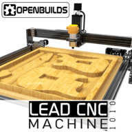
OpenBuilds LEAD CNC

Discussion in 'CNC Mills/Routers' started by MaryD, Nov 20, 2018.

  1. Peter Van Der Walt

    Peter Van Der Walt OpenBuilds Team
    Staff Member Moderator Builder Resident Builder

    Joined:
    Mar 1, 2017
    Messages:
    15,224
    Likes Received:
    4,349
    Glad you like it! :) Makes our day!
     
  2. Cloudbase Engineering

    Builder

    Joined:
    Apr 2, 2018
    Messages:
    16
    Likes Received:
    4
    Few quick questions.

    I keep coming back to thinking I need a machine. Had been considering the Workbee but curious what the differences are between the Lead and Workbee? Also my needs are 40" x 60" and curious if there will be a LEAD machine in that size. I am OK with running slow on the long axis to avoid leadscrew whip. Would prefer the long axis to be Dual Leadscrews on the bottom and the gantry to be the short travel axis.

    I have a shapeoko here at work and will be running a test this week to see if it will work for my needs. Mostly thin sheet aluminum and occasionally a few parts as thick as 1/2" 6061. Some wood as well. This is for an airplane build.
     
  3. ADW_01

    ADW_01 New
    Builder

    Joined:
    Nov 29, 2018
    Messages:
    16
    Likes Received:
    11
    I almost bought the shapeoko and Im glad I didnt. They claim to cut aluminum and it will but very slowly. You will get deflection and those belts will stretch. Compared to the OpenBuilds eco system you get total customization to suit your needs with a price point comparable to the Inventables and Shapeoko. So far from my experience, the customer support is great.
     
    Peter Van Der Walt likes this.
  4. Batcrave

    Batcrave Journeyman
    Builder

    Joined:
    Apr 20, 2018
    Messages:
    361
    Likes Received:
    166
    Day 31 - All Is Lost:
    The seas froth and bubble, as if they wish to wrap us in their lethal embrace. The mast is broken, the sails are in ruins, the ship is a junk. The hull split wide, as if opened by the builders. The captain has gone mad, muttering endlessly about "sea and sea". A sudden shout is heard over the tempest - "BAT OVERBOARD!"


    IMG_20181218_234104.jpg

    You guys don't mess around when it comes to packing, do you?

    Looks like it paid off... everything on the packing list is there (I checked. yup, every screw. every. last. ***** ** ***ing ****. screw. couldn't you have swapped out some of the self-tapping screws with self-counting screws? tapping is easy), but I didn't think to cross-check against the BOM, which is what actually matters. Oops. One thing that would've made the process a little easier would be including the name or SKU of the parts on the bag - there were a few things I had to look up on the site to identify.

    The wrench & the driver set don't show up on the list, but made it into the box anyhow. The rather nice looking "Made in USA" driver set, even. I didn't know there were metric drivers being made domestically. You don't mention that part on the store page, either.

    The finish on the rails did get a few scuffs and scratches already, though (some in transit, some because I'm clumsy) - one of the reasons I was having second thoughts about ordering the black version. Of course, those scuffs and scratches will soon be covered over by the scrapes and gouges of reckless use and/or collisions with wandering machine tools. Luckily the lighting's poor in the basement.

    On the whole, though, everything looks great... I'm sorely tempted to forego sleep and start building right now.


    -Bats
    ... --- ... ---. / ... .. -. -.- .. -. --. / .. -. / .- / ... . .- / --- ..-. / -... ..- -... -... .-.. . / .-- .-. .- .--. ---. / ... --- ... ---.
     
    MaryD, MFCarew and Mark Carew like this.
  5. Rob Mitchell

    Rob Mitchell Well-Known
    Builder

    Joined:
    Nov 29, 2015
    Messages:
    105
    Likes Received:
    35
    So I'm thinking of going the T-Slot waste board route this time. While looking at the 20x40 stiffeners on the bottom that run along y-axis it will become more challenging to add t-slots and MDF in combination while maximizing the available Z-axis height.

    Any suggestions?
     
  6. Trooper11040

    Builder

    Joined:
    Nov 23, 2018
    Messages:
    38
    Likes Received:
    18
    I’m planning on doing the same. I’ll pocket the t slots out of the actual wasteboard vs being on top of the wasteboard like my xcarve
     
  7. Josh Mascote

    Builder

    Joined:
    Jan 30, 2014
    Messages:
    39
    Likes Received:
    9
    Can someone clarify a bit more, I am not sure I follow how or where you would add these?
     
  8. Batcrave

    Batcrave Journeyman
    Builder

    Joined:
    Apr 20, 2018
    Messages:
    361
    Likes Received:
    166
    My thought was to mill slots into the wasteboard, and then lay in some T-track like these [ https://www.amazon.com/POWERTEC-71118-Double-Cut-Universal-Predrilled/dp/B074MN2CPL ]. I imagine it would also be possible to use 20x20 V-slot, but you'd have to have a pretty thick wasteboard.

    Another option - which I used on my last machine - was to drill a 1" grid of holes into the wasteboard for threaded inserts [ https://www.amazon.com/Z-Threaded-Hex-Flanged-Internal-Threads/dp/B002KT43MU/ - the $7 pack, not the $90 one - yikes! ] and then make Inventables-style clamps [ Clamp Set ] with various-length arms that screwed on. It's not something I'd recommend if T-track is an option, since it's more work and not nearly as versatile, but it's a viable alternative if you've sunk all your money into other parts & come up short on cash*. They also make a smaller target to hit when you send your tool cruising through the wasteboard, and are cheaper to replace. Not that I've ever done anything like that... this week.


    -Bats
    * in other words, it's probably what I'm going to end up doing yet again, at least for the first month or so.
     
  9. Craig Cavanaugh

    Builder

    Joined:
    Jul 7, 2014
    Messages:
    10
    Likes Received:
    8
    I've made a tweak to my build to support a split wasteboard. I built a flip-up torsion box to float over my table saw (space constraints). I left a large opening in the torsion box and exchanged the center 20x40 extrusion with a 40x40. The intent is to be able to roll the table saw out from underneath and route the long end of parts, etc. The opening in the torsion box will be used for fixturing location etc. It also gives me room for a 4th axis and vices as well.

    I placed t-nuts on the top sides to allow easy removal of the waste board,

    IMG_20181207_054921.jpg

    IMG_20181216_065139.jpg
     
    MaryD likes this.
  10. Jeff Stuart

    Builder

    Joined:
    Apr 2, 2016
    Messages:
    5
    Likes Received:
    3
    Humble noob here. Forgive me if this is the wrong place to post.

    First I congratulate Mark and Openbuilds on the Lead system. It's a great design (for my money) well executed. Packing as others noted was excellent. Putting it together was a very gratifying experience. Thanks.

    My kit included all the required parts. My only complaint was a handful of 5mm t-nuts didn't have threads cut all the way through. PITA having to undo work because a captive t-nut has a bad thread. I'm not blaming Openbuilds. They can't QC every t-nut that comes through the door. But if you could spank your supplier for me, I'd appreciate it.

    I'd also like to compliment Openbuilds on the control software and GCode webapp. Nicely done guys. It is especially nice to have software that runs on Linux, thank you very much. It over-torques my screws when businesses touting "open" only produce software that runs on proprietary monopolistic o/s. I know the economics, I've worked in software development for a long time. So again thanks for taking the trouble.

    I have questions. I'll ask 'em in what I hope is the right forum.
     
    Mark Carew and MaryD like this.
  11. Rob Mitchell

    Rob Mitchell Well-Known
    Builder

    Joined:
    Nov 29, 2015
    Messages:
    105
    Likes Received:
    35
    So basically the torsion box bed lies down flat on top of the table saw surface but flips up when there is a need to use the table saw. Need to see more photos of the setup. I have a few initial concerns about maintaining square over time but maybe you've already accounted for this the design.
     
  12. Craig Cavanaugh

    Builder

    Joined:
    Jul 7, 2014
    Messages:
    10
    Likes Received:
    8
    The box itself is quite rigid and for the most part 100% glue on all joining and laminated surfaces with screws added. I can't detect any flex and it's dead flat using a 4' level as a reference. May have gone overkill on hinges, but I wanted to be safe as use in a horizontal orientation is not ideal for loads.

    It sets 24" off the wall and is secured with a french cleat with a strip across the back side to secure it.

    All-in all, I'm quite happy with the end result. With a bit of luck, I'll have a dust boot ready and a 2nd stage bucket for the shop vac to begin surfacing the waste board and placing holes for threaded inserts..
     

    Attached Files:

    Batcrave likes this.
  13. Giarc

    Giarc OpenBuilds Team
    Staff Member Moderator Builder Resident Builder

    Joined:
    Jan 24, 2015
    Messages:
    3,028
    Likes Received:
    1,694
    If you want a great deal on aluminum T-track, look here. It is $5.25 per 24 inch piece. I went with the $8.54 per 4 foot piece. I put a 4 foot piece every 2.75 inches. I screwed them down with #6 pocket hole screws which you can get in bulk - and you need a lot. I originally wanted 10 of them, but the shipping was going to be about $15. You get free shipping at the $100 mark, so I threw in two more pieces, or should I say two free pieces. :) i will easily find a use for it.
     
    #133 Giarc, Dec 20, 2018
    Last edited: Dec 20, 2018
  14. Trooper11040

    Builder

    Joined:
    Nov 23, 2018
    Messages:
    38
    Likes Received:
    18
    So I did my first cut today. I’m trying to cut a pocket that is .76” wide and 30.75” long and .37 deep. My machine has been calibrated, stepper motors fine tuned..if I send the machine 450mm, I get 450mm on each axis.

    I’m cutting the pocket...I’m getting the correct distance, but I’m not getting the .76 width. I’m at 74.50”. I can’t figure out why especially since the distances are set perfect. Any advice?

    Dan
     
  15. Rob Mitchell

    Rob Mitchell Well-Known
    Builder

    Joined:
    Nov 29, 2015
    Messages:
    105
    Likes Received:
    35
    Do you have the correct size tool for the path you created. Maybe use caliber to check.
     
  16. Trooper11040

    Builder

    Joined:
    Nov 23, 2018
    Messages:
    38
    Likes Received:
    18
    I checked that as well...bit size is perfect in Vcarve according to my calipers
     
  17. Batcrave

    Batcrave Journeyman
    Builder

    Joined:
    Apr 20, 2018
    Messages:
    361
    Likes Received:
    166
    Did you check the size of the bit, or the size of the slot it actually cuts on a single pass? The two aren't always the same - runout & cheap bits can cause surprisingly large discrepancies, which can definitely lead to unexpected final dimensions. That usually shows up as incorrect dimensions in both X and Y, though. Not that I'd know anything about high-runout spindles and cheap bits on my CNC machines. Nope. Never. Probably. :rolleyes:

    Having the spindle mounted crookedly can cause errors in only one dimension, although I don't think the stock setup would let you mount it that crooked.

    Having play and/or backlash in one axis could do exactly what you describe (move the expected distance when you test it in a straight line, but give weird results with multiple passes), and having a loosely mounted spindle (or a spindle mount loose on the Z axis) might also do it.

    I've run into the same problem a number of times in the past, but most of those were caused by things that just don't apply to a solid, sturdy machine like this. Yours is solid and sturdy, right? Nothing loose or wiggly anywhere (including the workpiece), no wheels spinning loose without a preload, the axes don't more or shift when you push on them?

    If the machine's solid & square, my next inclination would be to glare suspiciously at the software, and see whether the model and/or toolpath it's creating are actually the same as the ones you're telling it to create, but it's been too long since I've worked with Vectric software to make any guesses.

    Also, there's a chance it would help to know what is it you're cutting, what size/type of bit (are you making one pass with a 3/4" bit, or a half dozen with a 1/8", allowing small errors to add up), and maybe your feed rate.


    -Bats
    [ and I'm going to assume that 74.50" was a typo. If you're really getting a >6ft wide slot when you aim for 3/4in, there are bigger problems at play ]
     
  18. Trooper11040

    Builder

    Joined:
    Nov 23, 2018
    Messages:
    38
    Likes Received:
    18
    Everything appears to be solid and done properly. I am cutting the wasteboard in an attempt to add 6 t tracks to the board to make it easier for clamping material down. 3/4” thick MDF, using a .25” EM
     
  19. Giarc

    Giarc OpenBuilds Team
    Staff Member Moderator Builder Resident Builder

    Joined:
    Jan 24, 2015
    Messages:
    3,028
    Likes Received:
    1,694
    Did you by chance select to leave stock for a finishing pass? If not, cut a single cutter width slot in a piece of scrap and measure it.

    How accurate are your calipers and where did you measure on the bit. You are off by 0.381mm which probably came about by compounding a much smaller error through multiple passes. I would say that most of my 3.175 mm (1/8") end mills actually measure in the range of 3.14 to 3.17. I do have a few that are 3.18 mm. One of my more expensive (1/8") cutters that I use for plastics is actually 3.11 mm. Before using a new cutter, I put them in my digital calipers and measure them on the cutting portion and slowly rotate them until the maximum diameter of the cutting edge is found and enter that into my CAM. I have found that the shaft may be dead on at 3.175, but the cutter is 3.16 or less.

    So, if I wanted to cut a 3/4 inch slot with my 1/8" endmill that is really 3.11mm - without knowing it was undersized - I would assume I could do it with six passes if I had no overlap. I would end up with an 18.66 mm slot or .7346".

    Also, I have ordered 10 packs of the same endmill from the same company and so far everyone I have measured has been slighly different sized. :confused:
     
    #139 Giarc, Dec 22, 2018
    Last edited: Dec 22, 2018
  20. JustinTime

    JustinTime Veteran
    Builder

    Joined:
    Dec 18, 2013
    Messages:
    784
    Likes Received:
    259
    That is not quite correct since your CAM program doesn't know that your bit is undersized and therefore will have each pass at the correct place. What you'll have is a thin wall (if at all) between the passes and overall the pocket will be only a little bit smaller than you had planned.
     
  21. Natesbox

    Natesbox New
    Builder

    Joined:
    Dec 26, 2014
    Messages:
    10
    Likes Received:
    10
    Can anyone give advice regarding connecting the xpro v3 to the digital loggers power strip? My lead machine is running great, but I'd like to get the spindle power control wired up.

    Also interested to hear what folks are using for a dust shoe, or if I should design and cut something out.

    Thanks!
     
  22. Giarc

    Giarc OpenBuilds Team
    Staff Member Moderator Builder Resident Builder

    Joined:
    Jan 24, 2015
    Messages:
    3,028
    Likes Received:
    1,694
    You are correct. In my mind I was imagining myself doing it by hand like when I used an edge guide to cut slots for shelves prior to having a CNC. My bad!
     
  23. Trooper11040

    Builder

    Joined:
    Nov 23, 2018
    Messages:
    38
    Likes Received:
    18
    Its finally done! T-Track installed, bump stop in...just needs dust collection and she will be working as my second machine!
     

    Attached Files:

  24. Rob Mitchell

    Rob Mitchell Well-Known
    Builder

    Joined:
    Nov 29, 2015
    Messages:
    105
    Likes Received:
    35
    Looks great, mind posting a few photos of the wire routing.
     
  25. Trooper11040

    Builder

    Joined:
    Nov 23, 2018
    Messages:
    38
    Likes Received:
    18
    The wire routing is basically the same as the video instructions. Only thing I added on my own was the IOT relat and a z probe which just run behind the machine to the controller. I’ll take photos for you later today
     
    Mark Carew likes this.
  26. valleskon

    valleskon New
    Builder

    Joined:
    Oct 28, 2018
    Messages:
    7
    Likes Received:
    4
    I connected the IoT switch to the xpro v3, pretty much guessed and hopped for the best but if you need help let me know i can take a picture on how i did it. the only think i dont know yet is how to wire the z prove or how to use it on the control, maybe i should use something else instead of the openBuild control.

    attaching images of the IoT :

    router cable added to the drag chain like the video shows.
    IMG_0767.JPG IMG_0768.JPG

    since the router cable is not that long i got an extension on HD i think was something like workshop extension, but i guess any would do.
    IMG_0769.JPG

    putting the things underneath the table, still working on the table ..
    IMG_0770.JPG

    as far as the wiring goes i did this if I remember correctly,
    used two wire cable, connected one to gnd and another on the output label SPL and connected that on the input of the IOT the green connector, it has labels for +/- (- is gnd, + to spl). so far its working great.

    upload_2018-12-28_17-43-45.png

    upload_2018-12-28_17-45-2.png
     
    #146 valleskon, Dec 28, 2018
    Last edited: Dec 28, 2018
  27. ADW_01

    ADW_01 New
    Builder

    Joined:
    Nov 29, 2018
    Messages:
    16
    Likes Received:
    11
    Any pictures of the probe setup?
     
  28. Natesbox

    Natesbox New
    Builder

    Joined:
    Dec 26, 2014
    Messages:
    10
    Likes Received:
    10
    Thanks! That works great! I also wired in my emergency stop button. If anyone is interested I uploaded some build pics here:

    OpenBuilds LEAD Machine 1010 40" x 40"

    Cheers!
     
  29. Matt190

    Matt190 New
    Builder

    Joined:
    Mar 5, 2018
    Messages:
    2
    Likes Received:
    0
    Looks great! I like the idea behind those T-tracks, where did you purchase them from?
     
  30. Trooper11040

    Builder

    Joined:
    Nov 23, 2018
    Messages:
    38
    Likes Received:
    18
    I got them on amazon. Powertec t track. I got the 36” tracks and cut them down to about 31”
     
    Matt190 likes this.

Share This Page

  1. This site uses cookies to help personalise content, tailor your experience and to keep you logged in if you register.
    By continuing to use this site, you are consenting to our use of cookies.
    Dismiss Notice