Welcome to Our Community

Some features disabled for guests. Register Today.

myOX : a 4' x 2' OX with potential

Discussion in 'CNC Mills/Routers' started by Serge E., Jun 19, 2014.

  1. GrayUK

    GrayUK Openbuilds Team Elder
    Staff Member Moderator Builder

    Joined:
    May 5, 2014
    Messages:
    1,668
    Likes Received:
    627
    Could have been a Bowler, but then it would be a load of BowlOx. Not good. :ROFL::ROFL::ROFL::ROFL:
    :zipit:
    Gray
     
  2. DiggerJ

    DiggerJ Journeyman
    Builder

    Joined:
    Sep 2, 2014
    Messages:
    412
    Likes Received:
    109
    Don't worry Gray, my new build will be built to make vertical dovetails, so it will be DTOX. LOL
     
  3. Serge E.

    Serge E. Journeyman
    Builder

    Joined:
    May 6, 2014
    Messages:
    730
    Likes Received:
    252
    That's right, it doesn't take much of an error at take off to overshoot the moon. It was my first thought when I saw how loose the 'tool' end was, even after correcting my errors. However, with some substantial redesign one should be able to get a firm and solid grasp of the tool. Like I said earlier, I'll start with 'normal' use : a bit of engraving, a bit of cutting, ... But I already have thoughts on how to make myOX have a steady hand ... or should I say, head. As for the bit's shaft, flexing and such ..., that's always going to be a problem and the heavy machines seem to have it under control when working huge chunk of much harder material. Scaling it down will be a challenge ... After all, the tool (router and bit) is basically off the far end of a diving board (reason it's so difficult to get precision when also going deep) ...

    That's right. As I said, my first go at the larger 'milling' will be for 1/10 remote control cars/trucks : mold forms to form the polycarbonate on. To be able to separate the thermoformed polycarbonate from the mold form, it needs precisely what you point out. Furthermore, as I pointed out earlier, with the open bottom, I could rig the work piece so I work on the top face, then do 90 degree rotation one way to work on a side face and flip 180 degrees to work on the opposite face.

    As a random example, the end product (after painting - this is a photo randomly picked off the internet by the way) :

    [​IMG]

    The rear wing is typically a glued/bolted on piece added after the fact.

    So it's basically chopping at a parallelepiped which could have parts cut out ahead of time (like the top of the hood portion).

    Notice how everything seems to slop away from the center top ? Working the mold form from the top, there is basically less than an inch of precise work to mill the top of the form (some rough cuts to remove material over the hood area). Same for each of the two sides (if work piece is rotated alternatively to work on each of those faces). The large gap from the front axle to bumper and same from the rear axle to bumper is actually the formed material cut out. The mold is a slop outward for an easy release. Yes, I know, 3-4 inches down, is still 3-4 inches down ...

    Oh, and being a hobby, I'm in no rush either. Of course, I don't want a smoke generator either. The tool speed was and is a major concern as the numbers I've see around points to lower rpm for slow and steady milling.

    So, here, we are basically saying the same thing. Careful rough (far from precise) milling to get general shape and then do a very shallow and possibly slow precision milling for the finishing touch ... taking into account such things as the tool (router and all) path.

    Yes, by that I always understood the flex to be in the opposite direction of the tool movement, so it can be in the X and Y. Z being the up and down, which should not be affected unless going down hard.

    The problem with doing slices will be the seams when it comes to the thermoforming of the polycarbonate. They will show, unless I do some extra work to fill and file them away. So not much different than 'hand' carving which takes away the cost incurred to build the machine. Sure, the rough shape will be done with more precision, if that makes sense, but no labour saving since the finishing will be done by hand anyways.

    I know and I welcome all views, opinions and suggestions. I'm a listener by nature, not that I will do what I'm told o_O After all, I'm relatively new to all aspects involved here. But I do cogitate a lot about all the aspects I can think of. Believe me, I do tend to over think things. Which doesn't necessarely get me any further than anyone else. I'll learn as I forge ahead ... It's the most interesting part of this journey, isn't ?
     
  4. Serge E.

    Serge E. Journeyman
    Builder

    Joined:
    May 6, 2014
    Messages:
    730
    Likes Received:
    252
    ROTFLMAO :ROFL::ROFL::ROFL:

    How they say again ... not quite orthodOX ?
     
  5. Serge E.

    Serge E. Journeyman
    Builder

    Joined:
    May 6, 2014
    Messages:
    730
    Likes Received:
    252
    You could of specialised in carving flowers ... that would be done with a phlOX ? o_O
     
  6. Serge E.

    Serge E. Journeyman
    Builder

    Joined:
    May 6, 2014
    Messages:
    730
    Likes Received:
    252
    As the day approaches for myOX to produce it's first load of (wood) chips, I'm thinking : better take the time to set those hard limit switches up.

    In the case of myOX, since it might be working, one day, in the deep end of its table, I'm planning on having adjustable 'stoppers' that can be positioned depending on the mode myOX finds itself in. Sure, there are "soft" limits which one could set and change as needed. But I know myself, and others, I'm bound to forget ...

    How does this sound to those who already have an OX, or any similar machine :

    A simple approach would be just a T-nut whose screw sticks out in the path of the switch which would be mounted on the moving portion of the machine. This way, the wiring is fixed - no changes needed or any wires to worry about from one setting to an other. I would just need to slide the T-nut in position, thus it becomes a "soft" hard limit - no programming to worry about forgetting. Seems too simple, no ? It could even work as a definite hard stopper since it would most likely also be in the way of a wheel - as done with runaway trains. It ain't going to be pretty if it manages to go beyond these stopper !

    The true "soft" limit could be set to the extreme limits of the working area and left alone. I could remember to change it. Thus the hard and soft limits would back each other out. First one hit stops everything ! The hand on the big red Emergency Stop in case all else fails, especially during the first few runs. Pulling power cable out of the outlet is the ultimate stop, if the breaker doesn't blow first.
     
  7. DiggerJ

    DiggerJ Journeyman
    Builder

    Joined:
    Sep 2, 2014
    Messages:
    412
    Likes Received:
    109
    Yeah, changed the name to Babe - The Big Blue (Laser) OX
     
  8. Serge E.

    Serge E. Journeyman
    Builder

    Joined:
    May 6, 2014
    Messages:
    730
    Likes Received:
    252
    Ok. So I'm pretty certain to go with the sliding stoppers, mounting the limit switches in appropriate fixed locations. Thus a change of position is just a matter of loosening a couple screws per axis, slide and tightening in new position.

    Y limit switches would be on the side nearest the controller which is mounted right on that Y plate. The adjustable stoppers would be on the respective V-slot. This makes for nice and short wiring : switch to switch to controller, just a few inches. I don't really need limits on both Y axis, do I ?

    X limit switches would be on either X plates the same way as the Y switches ... Stoppers on the respective V-slot. This gives short wire switch to switch (left and right), then a longer run down the chain track to the controller. This one might pick up noise along the way ... we'll soon find out how bad it gets. Some have reported problems, most are ok (not that I could find a lot of comments either way thus far).

    Z limit switches are going to be a bit tricker given less room to work with. They ideally should be on the front X gantry plate with stoppers on the back of the Z V-slot. There is not a whole lot of room between the two ! This one needs more thought. Going up, Z has to stop just before the tab like protrusion of the bottom plate hits the X plate's bottom edge - easy enough ... However, going down, ideally, the Z has to stop just a hair before the working end of the tool gouges the work surface (table top) OR, just as important, anything other than the working end of the tool hits anything in the way (ex: the Z V-slot or the router body hitting the piece being worked on). It needs a "safe work zone sensor" without it being in the way - "Shields are up, and holding !" I'm thinking : a "bumper" of sorts. Anything touching the bumper when it should not, triggers the limit. The trick is to adjust bumper's sensitivity... :eek: It needs to be rigid enough not to sag and cause false triggers ... yet flexible enough to sense an inappropriate hit while being out of the way. It also finds itself right in the middle of the action, so this means it needs to be able to ignore chips & dust ! Sounds like a challenge since "impossible" is to be read with a thought (') and a pause ( ) : I'm possible ! Of course, a volume based soft limit keeping track of tool, holder and work piece can do the job... or the G-code generator would have to be pretty fancy, no ? I like the bumper approach ... almost too simple/obvious.

    The trick, for all limit switches, is how to securely mount them not looking out of place. I have limits mounted on exposed PCB (offering debouncing and such) and switches all by themselves (much more compact).

    If you are using limit switches, how have you mounted them to your mutation of the OX ? Have you just abandoned them, keeping a sharp eye open and a hand close to the big emergency stop switch as your OX chips away at the work piece ?
     
  9. Serge E.

    Serge E. Journeyman
    Builder

    Joined:
    May 6, 2014
    Messages:
    730
    Likes Received:
    252
    myOX is now mounted (screwed) to the table, mostly to keep it on the table when chipping away. It is also suppose to keep it nice and square with two cross members... However, I have a bit of a problem :

    If I force the diagonals to be darn near equal, moving the X beam to far back or full front makes it way off, one side is substantially "short" (I mean a couple of inches shorter !) So I loosened the front, moved beam back and forth a few times, it looks a lot better, tightened everything. But the diagonals are now off ! This means the base is out of square, right ?

    My X (width) lengths of V-slot are not cut. They are as received. I presume and measured of equal length, the full 1500 mm.

    The Y lengths are cut by me and seem darn near equal. With Y gantry plates, the Y lengths are thus in just short of the full 1500mm on the base "X". This seems normal given inward offset of the wheels which ride on the Y lengths. Measuring spacing between the two Y shows they are parallel.

    So, if I ignore all of this, will I be milling what I think I'm milling. I just have a parallelepided instead of a nice square rectangle ? Opposite sides are parallel, but not square !

    In passing, with all the tweaking done on the Z to compensate the problem of the loose top wheel, this now seems to be quite acceptable with Z nice and stable sideways... The only movement left is the front to back since there is nothing (currently) to prevent this. Or my wheels are not quite tight enough. I might have to had eccentrics on the other 3 wheels of Z. Also, stretching vertically (ie. column) the wheel base would not hurt things.
     
  10. Serge E.

    Serge E. Journeyman
    Builder

    Joined:
    May 6, 2014
    Messages:
    730
    Likes Received:
    252
    Furthermore, I also reversed connections of one coil per stepper going the wrong way. So my Z goes up and down when asked to go up and down. X now also goes in the correct direction. However, inverting just one Y, one side seems to want back and forth "one" step (just shakes) while the other just sits there. This was how it behaved before inverting the one coil.

    Just thought of something, I ran out of one color of wire, so I used the same "sort of blue-green" for "blue" AND "green" at the far side Y stepper (the vibrating one). i might have those two crossed ? I thought such an error would just not step (?) As for the other side (frozen one), I have a loose wire. The 18 gage !! is not easy to slide in CNC xPro's connectors ... I know, I should be using 22 AWG or so. 18 was only gage found in town !! I'll have to remove the board from myOX to get a better angle to insert that hefty wire and fix a colour blind error. I might redo all of the wiring ... one day.

    Now to get my GRBL settings right ... :confused:

    Otherwise, almost o_O ready to make chips (basic engraving) ... even if the limit switches are not in ! :duh:
     
  11. Serge E.

    Serge E. Journeyman
    Builder

    Joined:
    May 6, 2014
    Messages:
    730
    Likes Received:
    252
    I know that part. But I still don't get the following observations :

    As I mentionned in my message, if I put it "square" - both opposing diagonals equal, then my X axis seems on an angle by inches (!) with no apparent way to adjust it. Keeping Y at either extremes, moving X slowly manually, it is way off (but not by quite as much) to the base X 20x40 V-slot. Something is definitely NOT square ...

    If I take it "out of square" (opposing diagonals off by ... maybe ... 1/2" or so, from memory I'm at work), X becomes nearly perpendicular to my Y (maybe an angle on its full 1500mm length o now less than ... 1/2". Here keeping Y at either extremes, moving X the router traces a nearly perfect parallel line with the base X 20x40 V-slot.

    :eek: What gives ? It doesn't seem to make sense. o_O

    It's as if my Y gantry plates / wheels assembly are both off at an angle ... the same angle at that. o_O

    I loosened the far Y gantry plate from all X beams (9 screws) and there seemed to be an improvement, however slight it was. If that helps anyone figuring out what could be wrong with myOX.

    I might have a crabOX - it walks sideways ! :ROFL::blackeye:

    In all likelyhood, it is something stupidly simple ... but beyond my midnight beagle eyes and half sleeping solitary neuron.

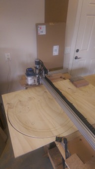
    As soon as I have all my steppers stepping properly (right scale, direction is fixed now), I'll mill a light criss-cross pattern on as big a piece of scrap wood or whatnot to see what comes out (maybe just have a floating pencil as the tool not to waste that big a piece of wood (nearly 2'x4', remember). If all is all nice and square, I'll leave it as is declaring the project "done". The rest will be enhancements as there is a growing list waiting for me.
     
  12. Balu

    Balu Well-Known
    Builder

    Joined:
    Apr 14, 2014
    Messages:
    81
    Likes Received:
    30
    Put a pen in the spindle (don't power it up ;) ) or attach it somewhere else and see if you can draw true circles and squares instead of cutting directly?
     
  13. Paruk

    Paruk Journeyman
    Builder

    Joined:
    Jul 13, 2014
    Messages:
    397
    Likes Received:
    149
    Serge, the V-slot profiles are roughly cut to length (as I found out when I received them) and therefor not exact enough to mount without making it fit. The 2 20x60 of 1000 mm I received were the same length but the 20x40 for the back of the gantry was about 5 mm shorter. If you mount it like that, the whole thing goes out of whack.

    Tomorrow I will cut the 3 together so they will have all exactly the same length. After that I will use a precision square to do the last fine tuning with the file, keeping them clamped together.

    By placing a MDF bottom in your OX, which has to be cut on exact dimensions and perfectly square, you will force the machine to be square. I will also attach the 20x80's for the Y to this plate to prevent them from flexing sideways. On top of that the sacrificial plate will be mounted.

    Hope this helps a bit.
     
  14. Serge E.

    Serge E. Journeyman
    Builder

    Joined:
    May 6, 2014
    Messages:
    730
    Likes Received:
    252
    Yap, that was my thought after clicking send ... just let the pen a bit loose in spindle just in case my Z is off as well ;( I'll just staple a large piece of paper on the work surface so it doesn't move.

    Doing a grid and a few concentric circles should show if all is well or very wrong :nailbite:
     
  15. DiggerJ

    DiggerJ Journeyman
    Builder

    Joined:
    Sep 2, 2014
    Messages:
    412
    Likes Received:
    109
    Remember, if you want a precision tool, you have to start with precision parts. It only take a very short amount of time to make sure your V-slot pieces are square and the same length. So far, in my build each piece of V-slot has had to be trimmed a wee bit.

    I just clamped the needed matched pairs together and squared and matched the ends. Very straight so far.
     
    Robert Hummel likes this.
  16. Serge E.

    Serge E. Journeyman
    Builder

    Joined:
    May 6, 2014
    Messages:
    730
    Likes Received:
    252
    I'm pretty certain I did all of that, down to carefully filling the ends. I also measured, as indicated, parallel runs. The one place I probably need to check is getting the Y lengths to sit square with the base/bottom X lengths. I also did not check the standard (uncut) length, presuming they would come as precise as can be right out of the factory. Part of myOX design, in its dimensions, was to minimize critical cuts (knowing my self). There is only 3 cuts : split a 1500 mm 20x80 for the Y (so not quite 750 mm each given blade/filling) and getting not quite 710 mm 20x40 for the spanners/cross members to keep the base X evenly parted for its full 1500 mm length.

    I'm not looking to mill critical parts for the space shuttle or such, but repeatable precision would be nice...

    My router seems a tad on the heavy side for the Z. On power off, it tends to "slide" down on its own. With power, it needs some pressure but not as much as I would of thought ... Is this partly due to my wheels not grasping the V-slot as firmly as they might need to (2 of the 3 eccentrics are at their limit already) ?

    Not only is starting with precision parts a good idea, but one needs to end with precision assembly as well. :oops: Neither seems worth the trouble without the other.

    Which controller was it that offered a self calibrating mode to attempt to adjust for deformations ? :rolleyes: It might just be what I need. Then again, it probably needs precision calibration reference points. Although, if I remember correctly, it based its calculation on creating its own reference points : a corner, an edge and some other points to even adjust to the work piece position, including angle as it sits on the work surface... Is it the Mk4 ? I forget ... too much reading on my part.

    I'll get there. My journey might just be longer than most ...
     
  17. DiggerJ

    DiggerJ Journeyman
    Builder

    Joined:
    Sep 2, 2014
    Messages:
    412
    Likes Received:
    109
    Well spoken. My post was just a gentle reminder for new builders (like myself) that it is hard to be too accurate. There are a pile of new builds going on, and if you read some of them, there seems to be some common "issues" and questions on the build process.
     
  18. DiggerJ

    DiggerJ Journeyman
    Builder

    Joined:
    Sep 2, 2014
    Messages:
    412
    Likes Received:
    109
    What router are you going to use? What Z-axis stepper motor?
     
  19. Serge E.

    Serge E. Journeyman
    Builder

    Joined:
    May 6, 2014
    Messages:
    730
    Likes Received:
    252
    Yap, I'm in that group too ... a greenhorn, as green as they come. :oops:

    There seems to be a surge of builds all of a sudden. This is great ...
     
  20. Serge E.

    Serge E. Journeyman
    Builder

    Joined:
    May 6, 2014
    Messages:
    730
    Likes Received:
    252
    I'm using a MasterCraft Digital 12 amps beast. Eh, it was on special at half price and I had phoney money (Canadian Tire dollars, it's like points elsewhere) so I didn't pay a hole lot for what seems a descent choice. I'll have to look up the details to be more precise on the specs ... they might be in an earlier post.

    For the Z, I kind of stuck to the OX design, so I have just a NEMA 17... I might have to eventually go with NEMA 23 upgrade. Probably when I start building a babyOX to carry around which would get the NEMA 17 and a much smaller router/spindle. But first, I have to get myOX running ...
     
  21. DiggerJ

    DiggerJ Journeyman
    Builder

    Joined:
    Sep 2, 2014
    Messages:
    412
    Likes Received:
    109
    Get a nema 23 and the proper top plate from Chris Laidlaw. Use the nema 17 on a lighter build (Me too). There is much response about the nema 17 being too small to support our bigger routers.

    I am ready to start wiring mine, as of this evening. Since my OX will be for router and laser, I think the nema 17 will move toward a plastic printer build.
     
  22. Serge E.

    Serge E. Journeyman
    Builder

    Joined:
    May 6, 2014
    Messages:
    730
    Likes Received:
    252
    I'm thinking about a quick tool change mount for myOX. You know, have a fixed plate on the Z, an other with the tool and its mount, then just something to attach latter firmly to former. Just unplug AC to tool and swap module Then again, one could achieve just about the same by getting the mounting kit from Chris and others, it's just four somewhat accessible screws ... but alignment would have to be adjusted at each 'module" change. More work ...
     
  23. Serge E.

    Serge E. Journeyman
    Builder

    Joined:
    May 6, 2014
    Messages:
    730
    Likes Received:
    252
    I have been going crosseyed checking and rechecking count of screws and such for the OXCalculator. So not much is going on to finish myOX in the last few nights.

    I really want to mount the limit switches before I ram the router where it should definitely not go! Maybe I can do just an handheld switch ... like they give you when you are in an hospital bed : "just push the button, we'll come !" Trick is to be able to reach the darn button and remember to press it :blackeye: Maybe it should be a "deadman switch" - release it and everything stops ... just don't fall asleep :sleepy: as you admire your OX hard at work. :confused: Maybe add the "driver's helper switch" : head tilts too much and ... everything stops ! :jawdrop: That would be just two switches with no special mounting, except maybe for that mercury switch stapled to the forehead. :eek:
     
  24. DiggerJ

    DiggerJ Journeyman
    Builder

    Joined:
    Sep 2, 2014
    Messages:
    412
    Likes Received:
    109
    That is sort of my plan, but I am making my laser mount to fit into the existing router mount from Chris Laidlaw.

    Simply a round aluminum piece that will hold the laser and fit into the lower router mount rung. Slide router out, insert laser, snug lower mount rung, plug in and blast away.
     
  25. Serge E.

    Serge E. Journeyman
    Builder

    Joined:
    May 6, 2014
    Messages:
    730
    Likes Received:
    252
    Sounds like a solid plan, especially considering the laser will not be subject to forces, other than a few G whipping about to and fro, left and right in its play area.

    Can't wait to see it at work !
     
  26. Serge E.

    Serge E. Journeyman
    Builder

    Joined:
    May 6, 2014
    Messages:
    730
    Likes Received:
    252
    Houston, we have take off ! :thumbsup:

    Could not get quite the right numbers from the GRBL calculators for some odd reason. A bit of playing around with the X/Y and Z steps per mm and it looks like we are just about dead on ! :thumbsup:

    Z looks sweet, but it is with a number way different than the one given by calculators. Maybe I just don't get the formulae o_O I'll have to run through them one more time when I'm not half asleep :sleepy: The calculator says 800, but I have to use 200 ! Maybe I need to double check the jumpers for the microsteps on Z ? All four seem set to the same 1/8 though ...

    X looks sweet as well. The calculator gave the right number first time out. I must of messed Z somehow ...

    Y, well, he's not quite there. The stepping is right. As to be, same steppers as X. So same step count per mm, right. The probem here seems to be two fold. First, I'm not quite square, but I should be sort of ok since the two Y lengths are parallel. Going back and forth, should move Y without issues, right ? The second, and the culprit here, is that there is some flexing over 1500 mm length of X ... maybe power to the Y steppers is not equal ??

    Of course, for now it is low res pen and paper tests : drawing a square and the two diagonals ... Somehow, with that slight difference between the two Y steppers, there is a bit of an offset, one seems to start/stop before the other !

    Almost there ... I can smell the (wood) chips from here ! :cool:
     
  27. Serge E.

    Serge E. Journeyman
    Builder

    Joined:
    May 6, 2014
    Messages:
    730
    Likes Received:
    252
    Having slept a few hours, the ACME screw for Z is (suppose to be) a 4 start which gives 800/4 (?) and ... tada ... 200, myOX magic Z number. Is that right ? I must of forgot to include this detail...

    Now to figure out what is 'wrong' with my Y. The far stepper is really loud compared to the near Y stepper. In my colour blindness I had the blueish green and greenish blue wires inverted up until late last night. Could I have :eek: damaged the stepper by doing the bits of testing all this time with these swapped connections (red-green and black-blue instead of red-blue and black-green) ? How could the stepper even work like that ?!? o_O:blackeye::oops:

    Like tires on a vehicle, the two Y steppers should be relatively matched, right ? So if I want to fix, if that is the problem, the one Y I should get an exact replacement or change both of them, right ?

    One other possibility is that the wiring to the far Y is using solid core, instead of twisted, and gage also different. It does not have any movement - goes from far Y, through X beam to controller on same moving assembly. Could being a much longer run, a different type and gage introduce issue with signal quality to that far Y ? :duh:

    Like someone mentioned in a post read in some other build not too long ago : this isn't art, it is a science. Not rocket science, mind you, but science nonetheless.

    Maybe I should adjust timing related parameters of GRBL to see if it compensates ... In science, experimentation is part of life. That sounds like a artsy type of comment. :banghead:

    I still have the stiffness issue with my long X. The double beam carrying the X/Z carriage looks ok (for me at least). I even have the 3rd beam in place, the one to help keep the Y plates parted. However, all three are oriented vertically... I would of thought the 3rd should be horizontal. You know, so it works against the sort of problem facing myOX ?

    So close, yet not quite there.

    Looking forward to your comments, suggestions, feedback ... and even jokes at this point.
     
  28. dddman

    dddman Journeyman
    Builder

    Joined:
    Mar 2, 2014
    Messages:
    468
    Likes Received:
    187
    Did you try to bolt your two 20x60 X beams together?
     
  29. Serge E.

    Serge E. Journeyman
    Builder

    Joined:
    May 6, 2014
    Messages:
    730
    Likes Received:
    252
    Honestly ... NO. Do you think that would help my situation ? :rolleyes: It might help prevent slipage between the two ... worth giving a shot. Thanks.

    I just hate having to drill holes in these nice looking V-slots. My 3D printer (a Micro) will not arrive for an other few months (make that probably 5 months !) Anyone selling the thingies I could slide between the two X beams so I don't have to wait for my 3D printer to come in ? It would look so much better, no ?

    Presentation does count ...
     
  30. dddman

    dddman Journeyman
    Builder

    Joined:
    Mar 2, 2014
    Messages:
    468
    Likes Received:
    187
    Do you mean the v-slot covers? I have a 3d printer so if you have the .stl (or the .scad) we could arrange something :). According to I don't remember who... your X beam will be 4 times stiffer if you bolt your 20x60 together.
     

Share This Page

  1. This site uses cookies to help personalise content, tailor your experience and to keep you logged in if you register.
    By continuing to use this site, you are consenting to our use of cookies.
    Dismiss Notice