Welcome to Our Community

Some features disabled for guests. Register Today.

myOX : a 4' x 2' OX with potential

Discussion in 'CNC Mills/Routers' started by Serge E., Jun 19, 2014.

  1. Serge E.

    Serge E. Journeyman
    Builder

    Joined:
    May 6, 2014
    Messages:
    730
    Likes Received:
    252
    No it was like a connecting rail which is "forced" into track of the V-slot ... a bit like an I beam which holds the two beams together, hidden in the slots. I could not find in the ressources, but remember seeing a post about it. I'll have to search for it ...

    I might have to get the drill out and bolt them together. What was it, drill hole to thread as a M5 with lock nut or just a T-nut on the other side ?

    Would be nice if there was a 40x60 version of V-slot, eh ?
     
  2. Rick 2.0

    Rick 2.0 OpenBuilds Team
    Staff Member Moderator Builder Resident Builder

    Joined:
    Dec 20, 2013
    Messages:
    2,892
    Likes Received:
    1,551
    I believe this is what you were looking for: http://www.openbuilds.com/resources/v-slot-connector.40/. I'm not sure they will be rigid enough to make the two members truly act as one but are worth a try. The easy solution would be bonding the two rails with JB weld or epoxy. Fastening the rails together using M5x8mm screws and T-nuts hidden in the abutting slots is also an option but you will need to drill 4 mm holes through the center of the rail at each location to be able to get a hex driver through to each screw head to tighten them down.
     
  3. DiggerJ

    DiggerJ Journeyman
    Builder

    Joined:
    Sep 2, 2014
    Messages:
    412
    Likes Received:
    109
    [QUOTE="Would be nice if there was a 40x60 version of V-slot, eh ?[/QUOTE]

    Since the OX plan calls for doubled 20x60...The 40x60 would make a stronger rail for a bunch of builds, and I suspect it might end up as other things like legs for the tables, over-gantry arms for dust collection, a boom tube for fourth axis, and who knows what else.

    Digger
     
  4. Serge E.

    Serge E. Journeyman
    Builder

    Joined:
    May 6, 2014
    Messages:
    730
    Likes Received:
    252
    That's the thinkofabob I was thinking of. (sorry for my highly technical terms)

    Yes, if made of prnted plastic, even tightly set into the two V-slot, it might not give 'ultimate' stiffness over time. Worth looking into it. One key advantage here is that all exposed tracks remain free of obstructions.

    If I bolt the two V-slots together, I would look at hiding, as much as possible, the added hardware ... The few examples found (ex: http://www.openbuilds.com/threads/cnc-mill-i-beam-concept.653/#post-6793) would get in the way if one needs the track.

    Ideally, we could all use some 40x60 V-slot for those long X axis. :rolleyes: Maybe even 40x80 for long Y axis. :cool:Should we get into a KickStarter to get the extrusion molds done and paid for ? :thumbsup: Could maybe get into a 2000, 2500 or maybe even 3000 mm length at the same time. Of course, shipping those suckers could cost pretty penny or two.
     
    silopolis likes this.
  5. Serge E.

    Serge E. Journeyman
    Builder

    Joined:
    May 6, 2014
    Messages:
    730
    Likes Received:
    252
    Since the OX plan calls for doubled 20x60...The 40x60 would make a stronger rail for a bunch of builds, and I suspect it might end up as other things like legs for the tables, over-gantry arms for dust collection, a boom tube for fourth axis, and who knows what else.

    Digger[/QUOTE]

    Yap ... lots of potential uses and easier than bolting 20x together.
     
  6. Rick 2.0

    Rick 2.0 OpenBuilds Team
    Staff Member Moderator Builder Resident Builder

    Joined:
    Dec 20, 2013
    Messages:
    2,892
    Likes Received:
    1,551
    Serge, I was referring to the next picture down from the one you selected. Except with washers under the head of the screw.
     
  7. Serge E.

    Serge E. Journeyman
    Builder

    Joined:
    May 6, 2014
    Messages:
    730
    Likes Received:
    252
    Has anyone seen this 5 axis "DIY" build - the 5axisMaker ?

    It's currently on KickStarter, out of England though. Somewhat expensive for my budget, but I 'want' !

    [​IMG]

    Interesting parts include :
    • uses aluminum extrusion (not V-slot from what I can see - maybe Mark can work a deal with them ?)
    • uses "open source" 5 axis software (I didn't know there was some) plus their twist for ANY 5-axis !
    • could build a version using V-slot and a good 5 axis controller (6 drivers since Y needs two steppers)
    • shows a descend Z travel can be achieved - uses a different design though
    Not so interesting :
    • cost, as listed in KickStarter is still quite high so it can only get higher after KickStarter
    • work area is limited to 40cm x 40cm x 40cm (about 1.3' x 1.3' x 1.3') on base unit
    • substantial increase in price to get a better working volume : 100cm x 100cm x 50cm (much better)
    Nonetheless, I will give my little bit of contribution ... enough to apparently get all releases of the 5-axis Gcode generator (YES ! :thumbsup::cool:) By the time it comes out (April 2015) I should be more than ready to upgrade myOX to a full 5-axis :rolleyes: ... ok, maybe just do a myOX-3D :thumbsup:

    Maybe a few others will be interested in the 5-axis Gcode generator as well, so thought to share the project ...

    Which brings up a (stupid) question on my part : is there a place here to talk about projects without having to start a build or a resource ? I most likely didn't look hard enough (or at all :oops:) ...
     
  8. Mark Carew

    Mark Carew OpenBuilds Team
    Staff Member Moderator Builder Resident Builder

    Joined:
    Jun 28, 2013
    Messages:
    2,758
    Likes Received:
    2,441
    I have seen this project and its like you I too think it super cool :thumbsup:
    I was under the impression it was being run under a Grasshopper script for Rhino, could be wrong as I did a quick glance

    Now that would be a cool build indeed! I am still looking to see if someone is going do a rotary axis for the OX ;)

    Here you go in the forum under
    SHARE BUILD IDEAS
    Share your machine ideas and concepts with others.
    Concepts and Ideas
    http://www.openbuilds.com/forums/concepts-and-ideas.15/
     
    Robert Hummel likes this.
  9. Serge E.

    Serge E. Journeyman
    Builder

    Joined:
    May 6, 2014
    Messages:
    730
    Likes Received:
    252
    I soon as I have myOX ready to mill, it will be ready for a manual 'rotary axis' (4th axis) down IN the table. It would be a simple rotating sub-table to mill 'surface' of a block of material to shap 'simple' molds for RC body thermoforming (an other project I should start a build on, even if it has no V-slot).

    I actually went to the Forums section moments after my post and noticed I can start a new thread in various forums. I picked the... Other Builds since it is a build (not on here, but elsewhere on the planet). But, yes, Shared build ideas is a good spot as well. Can I (or you) move the thread I started ? This is way off topic, let's move to a conversation from here.
     
  10. Serge E.

    Serge E. Journeyman
    Builder

    Joined:
    May 6, 2014
    Messages:
    730
    Likes Received:
    252
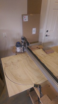
    myOX is almost done (as in ready to mill). It has done several hand guided (GRBLController on MacBook) drawings (pen in router). Nothing too impressive - just boxes, diagonals, circles (nice !) Feed speed seems good even beyond 1500 (just a pen sliding on paper/wood).

    X axis seems dead on no matter what. Feels good as it shows it can be done (by me at that !) The X beam are not visibly flexing in any direction, although when Y is travelling, one side starts/stops a bit earlier than other

    Z axis is working fine although there is very little load at this point. When drawing on an irregular surface, the pen (bare refill with electrical tape to reach proper diameter for collet) is bending rather than seeing Z move ! That is nice to see (with a pen, not a bit !) However, myOX still has an issue with the eccentrics not quite tight enough to properly guide the V-slot. Short term fix will be to add eccentrics on the other side and hope it does the trick to graduate from drawing with a pen to milling 2.5D with a real tool. Right now, the slack is visible - can see the wheels aren't quite doing what they should. Movement side to side is very minimal, but front/back is more pronounced. Neither is good for working under load and with any hopes of precision.

    Z is running a bit hot. I probably need to turn down amps to it (?) CNC xPro came with all four set to default which seems to be fine for the NEMA 23 steppers.

    Y axis has a problem and I really don't like the fact the far end stepper is much noisier than the other Y stepper and the identical X stepper. As mentioned earlier, I had the blue and green wires inverted (!) Could this have done any damage to the stepper ? or the driver ? When stepping 100mm, almost all of the time it moves only 93mm or so. GRBL is setup the same for X and Y given they use the same steppers, GT3, etc. If it was missing steps, it would be inconsistent, right ?

    The Y beams are parallel, so even if one is longer than the other - as in slightly by the base not being perfectly squared, they remain parallel and travel along the axis is not affected as long as both steppers are stepping in sync (speed, direction and distance). The base being perfectly square only means both Y beans are parallel & perpendicular to the spanners (X of base). But the latter can be crooked as they serve no other purpose than: keep the Y apart and hold the spoiler/work surface, nothing rides on them. They do have to be rigid. They're designs with the Y bolded down with no X span, other than the surface being bolted to (more of an X plane).

    A little detail holding me back to actually milling a piece of wood (or any other material) : I need a bit ! Router has 1/2" and 1/4" collets, but the bargain bits I purchased for trials are all 1/8" :banghead::blackeye::duh: For some reason I was thinking more like a drill, takes anything that fits with chock squeezing in to hold the bit. Told you I was green. Oh wait, I've got a better excuse ... initially I was thinking of using the 'dremel' with flex adapter. Ya, that's it ! And I'll stick to that excuse. o_O

    So I'll need to do a bit of shopping. Local as soon as tomorrow to get at least one bit to start making chips. Did spot a few interesting deals on the web. Even found some nice 4.5" and 6.5" bits to help going deep (top comes off the table since OX's standard configuration of Z doesn't allow for these !)

    http://www.2linc.com/endmills/endmills_standard_1-8.htm
    http://www.2linc.com/engraving/parallel_bn_1-8.htm

    Any thoughts on such bits (end mills / tools / ...) ? I do have a large 'surfacing' bit I could try ... skim the work / table surface see how much is removed :nailbite:

    This might give me time to actually install the limit switches. As I used GRBLcontroller to draw, I really want my X and Y limits to be adjustable. It would let me bound the work area to smaller than what myOX can do & it will make zeroing within those adjustable bounds much easier !

    Which brings up a few observations as I scanned for various sample Gcode files. It would be good to keep in mind by those as green as me.
    1. using someone's Gcode files IS dangerous! They are made for their machine not yours. At least some have a header indicating their centre, their orientation, if inches or mm are used, etc. Better have the limit switches on the ready AND scan the code for obvious signs of trouble for your machine AND do "air cut" with no tools nor work piece in the way.
    2. many seem to use the centre of the work area as their X and Y origins, while the top of the work piece becomes Z's origin (!) What if I start from a blank which is a bit bigger ? I always thought X, Y, Z "0" was the start point with the work piece contained in the positive quadrant ...
    3. setting up soft bounds is not a bad idea as limit switches could fail and the Gcode file could be off your work area
    4. not all controllers interpret some Gcode exactly the same way (apparently - from warnings of some).
    5. not all Gcode are supported by all controllers (!) You might get unexpected behaviour/results.
    6. learn to read at least the most common Gcode, most of it is easy enough (arc & circles can be cryptic)
    7. once ready to run the code, keep a hand near the big red Emergency button (or next best equivalent)
    Again, these points may seem obvious to those who have already made several cuts. Some where not quite obvious to me (I would of expected a Gcode file to be much more universal : origin always at same spot and people worked only in positive quadrant - even with myOX, and its potential to go below the table surface, I was expecting to have origin always at a bottom corner.

    Midnight rambling... sorry. :sleepy:
     
    JustinTime likes this.
  11. Robert Hummel

    Robert Hummel Custom Builder
    Moderator

    Joined:
    Nov 14, 2013
    Messages:
    978
    Likes Received:
    715
    I would not go to all eccentrics on the Z assembly
    Take things apart, then drill the 5 mm holes that mount the blocks a tad bigger 5.13mm
    Then when tightening the blocks squeeze inward.
    The reason I say this is because the 3 wheels that mount solid are meant for alignment.
    With 6 eccentrics I think your going to be unhappy with the results and driving your self nuts getting things to be square and tight.
     
  12. Serge E.

    Serge E. Journeyman
    Builder

    Joined:
    May 6, 2014
    Messages:
    730
    Likes Received:
    252
    Thanks, it's just that I keep finding loads of "pre made" Gcode files on the 'net to "test your machine" with. A few interesting files, having looked into them before sending them over to myOX, had there centre in middle. myOX, from where I stood, had it in bottom left corner. So very first move would of destroyed something :blackeye:

    It pleasant to find Gcode files since one doesn't have to go through design and Gcode generation. But taking such shortcuts, without being as careful as exploring uncharted/unfamiliar lands, can be costly at time... My rush comes from the success, not the taking risks.

    Limit switches are definitely going up before I go much further especially before I load any Gcode files. Right now I just use GRBLcontroller manually, so one command at a time, usually short moves all around centre of my large working area. Call them 'warm ups' to see how Gcode and myOX behave, my learning curve usually starts real real real slow and then, once comfortable, I go for it.

    So, as close to being 'done' to a stage of milling something, myOX remains "in progress" :cry:
     
  13. Serge E.

    Serge E. Journeyman
    Builder

    Joined:
    May 6, 2014
    Messages:
    730
    Likes Received:
    252
    Good point AND it is why I have been holding off to using three more eccentrics. Like you point out, with all wheels on eccentrics, nothing is in place to have a straight vertical reference. Alignment will be horrendous, where even possible.

    Time to break out the old ShopSmith (was my dad's) into its drill press configuration :
    [​IMG]
    (I have a much older version, looks pretty much identical, and works fine ... the machine forces one to plan work real carefully as you don't want to reconfigure it between every steps of a job : do cuts, then drill, ...).
     
    GrayUK and Robert Hummel like this.
  14. Mark Carew

    Mark Carew OpenBuilds Team
    Staff Member Moderator Builder Resident Builder

    Joined:
    Jun 28, 2013
    Messages:
    2,758
    Likes Received:
    2,441
    I had an older version of the shop smith as well :) Had fun with it
     
  15. Johan Schreiner

    Builder

    Joined:
    Dec 7, 2013
    Messages:
    5
    Likes Received:
    1
    Hi,
    If you want to bolt your to 20x60 x-beams together: drill a hole just big enough to get your hex key through one of the beams. Then screw a 8mm buttonhead screw into a t-nut. Slide the t-nut into the slot of the beam without hole and the head of the screw into the other. Slide the nut down so that it alignes with the hole you drilled, and tighten the screw through the hole. I have done this with 6 screws on my x-beam. It is a little bit difficult to aligne all the screws at the same time, but it works great!

    Johan
     
  16. Serge E.

    Serge E. Journeyman
    Builder

    Joined:
    May 6, 2014
    Messages:
    730
    Likes Received:
    252
    Sweet ... and virtually invisible, short of the holes for the hex key. Could always add a pit of silicon so dust or chips don't collect through those holes.

    At this stage, I would have to take both X beams out, one completely to drill the holes and the other enough for sliding in the t-nut portion. Hmmm ... I have some wiring going through the far X beam ... oh well. :oops:
     
  17. Steve123

    Steve123 New
    Builder

    Joined:
    Feb 11, 2014
    Messages:
    35
    Likes Received:
    12
    Yap ... lots of potential uses and easier than bolting 20x together.[/QUOTE]

    I see CNC Mogul now has 40x60 makerslide type rail. I hope he will opensource his design as he posted on the shapeoko forum.
     
  18. Serge E.

    Serge E. Journeyman
    Builder

    Joined:
    May 6, 2014
    Messages:
    730
    Likes Received:
    252
    I think I figured out at least two factors to my Y movement problem : one side "bounces" on start/stops causing a slight crab like start/stop motion most pronounced when moved manually.

    first, the Y gantry plates are slightly at an angle with the 3 vertical 20x60 X beams... The plates are not squared with the X beams. It's not much, but enough not to help.

    Then, out of curiosity, I have measured a spare full length piece of 20x40, spec'ed at 1500 mm. Guess what ?:eek:It measures 1505 mm, not 1500 mm. o_O So, if my three X beams are not of equal length, that 5 mm will twist a bit the Y plates ... they could act as a bit of a spring (?) causing the "bounce". Note, I did not get the three length at the same time nor from the same source. So possible they come from a different batch.

    Goes to show one needs to measure EVEN the pre-cut lengths. It's the old : "measure twice, cut once".

    When I measure from the outside of one Y gantry plate to the other, at three different accessible spots : at mid-top, mid-back and mid-front slope, I get three different measurements (with the same tape so any error should be equal) : 1517+, 1516=, 1516.5- mm respectively. The square is also showing about 1 mm gap outward at far Y plate (70 mm out from front X beam) and, oddly enough, 1 mm inward at near Y plate (also from front X beam, 70 mm length to edge of Y plate slope, that's just below stepper's bottom screws' head). My square is aging, I'll get a new one to double check things.

    Note, as long as the Y is moving, the problem seems to have no effect. It is only when movement starts/stops, with a long enough pause, that the 'bounce' (slight twist back) shows up.

    So, just for the fun of it, I clamped the spare length of 20x40 horizontally to the rear most X beam (it's vertical like the other two which are twinned, but not bolted together). Only two clamps are used: near end and middle It is obviously longer since I can't slide it down parallel to the existing piece. EVEN with the hammer in hand ! Nonetheless, miracle! o_O, when the controller moves back and forth in the Y direction, with our without long pauses, there is no more bounce. It's just as smooth as silk. So my thought of having the third X beam changed to an horizontal position is not that bad of an idea.

    It's like an engineered beam with two 2x horizontally with a wide piece of OSB sandwiched vertically. It creates resistance in both X and Y plans. The 2x want to flex up and down, but the wide OSB is not letting them ... The OSB would flex left and right, being relatively thin, but the 2x are not letting it. Strong AND light, spanning the full length of your house's floors at that.

    To rotate the third X beam 90 degrees, placing it horizontally, requires a couple of extra holes in the Y plates ... For now I'll live with the bounce since I'm just playing with myOX. I'll need to change a few T-nuts (over tight and they strip !) and such when ready to strip myOX down for a rebuild.

    The situation might not show or be pronounced enough with other configurations of an OX. I have the X at the current maximum of 1500 (or so) mm.
     
  19. Paruk

    Paruk Journeyman
    Builder

    Joined:
    Jul 13, 2014
    Messages:
    397
    Likes Received:
    149
    "Goes to show one needs to measure EVEN the pre-cut lengths. It's the old : "measure twice, cut once"."

    I tried to explain that to you about a week ago, as Digger tried too. Could have saved you the trouble by following up to that. So, I'll give it a last try to help.

    You can check your square by holding it against a straight edge of a plate of wood, draw a line along it, then flip over the square, hold it against the line and see if it is lining up exactly. If so, the problem is not your square. If not, you can adjust the square until it is perfectly square again. Youtube has many videos to show how. Google for it.

    "EVEN with the hammer in hand !"
    If you need a hammer, you don't know what you're doing and it is a very bad sign. As a former white yacht captain, I simply kicked any engineer of the ship that used a hammer. Unless he used it for driving nails in or making center holes with a center punch.
     
    DiggerJ likes this.
  20. bobt

    bobt Well-Known
    Builder

    Joined:
    Dec 4, 2013
    Messages:
    89
    Likes Received:
    38
    Yes but if the engineer is holding the hammer he might hit the captain just by accident. You never know about engineers. And every engineer knows that measuring twice is not enough. Square or cube the count and the engineer is just getting started. You did say "Precisely", did you not.

    Bob
     
    Balu and Serge E. like this.
  21. Serge E.

    Serge E. Journeyman
    Builder

    Joined:
    May 6, 2014
    Messages:
    730
    Likes Received:
    252
    I must of missed the part about having to measure 'from factory' spec'ed lengths. My apologies if I did. I learn quickly, you just have to explain slowly. o_O ... :ROFL: I should of known better since 2x4s are closer to 1.5x3.5, depending on the mill and the day of the week; a size 8 shoe from one manufacturer is not quite a size 8 of an other; etc. And, yes, there is a metric pound ! :duh:

    Had checked my old square and it seemed fine. Even did the flip when checking myOX. In fact, I always do the flip, even with a level. Just in case, got a second opinion. Got a brand new square, one with ruler markings and a 45 degree as well. It gave same results. I always wanted one of those anyways. So this was as good as an excuse as I could find to get one ... and it was 50% off (price, not precision).

    As for the part with the hammer, it was tongue in cheek as I'm not the type to fit square pegs in round holes ... at least not with a hammer, maybe a chisel, bit of filing and ... :ROFL: Seriously, as soon as I saw the thing would not fit, I left it angled and just clamp what I could (reason for only two clamps, one end and the middle, there was no way to clamp the other end). But it was enough to show me that having that back V-slot horizontal instead of vertical would make a (good) difference at least to my situation.

    Then again, you might of kick the hammer swinging engineer off the yacht, even if it wasn't white o_O, if the nails were driven at the wrong spots ... er ... is that water ? :ROFL:

    For all that matters, there are people doing work of arts with chainsaws, of all the tools to choose for precision sculpting. Goes to show that it's not the tool that makes the difference, but how it is used.

    Anyways, my two lengths of 20x80 for the Y beams are not perfectly equal in length. One is a fat 751 mm, while other is skinny 751 mm. Notice how that is a tad over 1500 mm, not even counting the lost material from sawing in two ? Anyways, thus using the good old diagonals to make the whole machine square will not give perfect results... In fact, it could make the Ys loose their parallelism. If two straight lines are equal distance apart, they are parallel. The two lengths of 20x40 which only serves to keep the Ys parted and as a stand to rest the spoiler board upon, do not need to be bang on parallel ... Heck, they'll be out of sight as well (under spoiler board). The X assembly rides on the Y not the 20x40. Yes, making the 20x40s as parallel as possible makes for good craftsmanship. If they are also not of equal length, then the diagonals will also suffer. I'm always aiming for "perfect". Recognising I'm still and will forever be learning. myOX is my very first machine. There will be modifications and rebuilds and offsprings of myOX. Each will be better than the previous ... With everyone of them, I'll be learning even more.

    The journey is more than half the fun.
     
  22. Serge E.

    Serge E. Journeyman
    Builder

    Joined:
    May 6, 2014
    Messages:
    730
    Likes Received:
    252
    :) Here is a quick and dirty (no, not that kind of dirty) video of myOX doing it's first public test pattern. The router, not spinning, is grasping a chopped Ikea pencil wrapped in electrical tape to properly fit in 1/2" collet. Unfortunately, it's sharpened by hand as I crushed the tip in the previous run (forgot to raise Z before starting the program which lowers it, figures! :oops:) That will teach me for not having the limit switches installed !


    The piece of paper was taped unto a piece of 1/8" thick wood (somewhat curved, sorry) which was nailed to the table. The paper, expecting no less, moved a bit early on... So I held it, the paper, as best as I could for the rest of the run (keeping all of my fingers safe, of course).

    Anyways, the pattern is a simple 50mm x 50mm square with diagonals : check squareness... as the square is suppose to be exactly 50x50. The 'program' runs through several overlapping iterations, changing feed rate along the way, just to check effects on alignment and such. Looks pretty good, no ? I should run diagonals backwards as well ...

    Can you hear that far Y stepper ? I don't like the sounds of that, as mentioned a few times earlier. But it is working and myOX is my very first machine, ever - my prototype ... I'm happy. :thumbsup: It might get a stepper transplant later ...

    Even though I left the 'bounce' in the Y movement, which disappears when moving non stop (or just about non stop) ... It's looking good, no ? I did test circles as well. But I need to fix the paper better before going public with that. :duh:

    So I ran (actually drove) to the nearest Home Depot and ... didn't get the Freud 1/4" shaft 1/8" straight router bit. 20$ ! CanadianTire, my next stop, had one (not Freud) for 8$ which I didn't have to pay with real money given I have plenty of Canadian Tire money :) (call them points). Back home I headed ...

    Shoot ... the wife was already back from her out of town travel. My stuff was spread in the garage, as I was also prep'ing for fabricating supports for the limit switches ... ya, they still remain in the box. They won't help much there, will they ? I'm also prep'ing to redo my plexyglass shields in SketchUp and cut them with myOX. :rolleyes:

    I also found a large piece of 3/4" MDF (or HDF as it looks of higher density than the regular stuff) ... free ! :) Should have in my hot little hands tomorrow, I hope.

    Tomorrow is an other day ... and, best of all, this weekend is a long weekend ! I'll be making chips for certain, wood chips that is !

    Can I call myOX "completed" at this point, or should I wait for the limit switches to be installed and wood chips to fly ?
     

    Attached Files:

    #112 Serge E., Oct 9, 2014
    Last edited: Oct 9, 2014
  23. Serge E.

    Serge E. Journeyman
    Builder

    Joined:
    May 6, 2014
    Messages:
    730
    Likes Received:
    252
    How about a YouTube version of that video ?

     
  24. GrayUK

    GrayUK Openbuilds Team Elder
    Staff Member Moderator Builder

    Joined:
    May 5, 2014
    Messages:
    1,668
    Likes Received:
    627
    Are you happy with the sound it makes?

    Do you put the slight variation of the lines down to the paper moving?

    Gray
     
  25. DiggerJ

    DiggerJ Journeyman
    Builder

    Joined:
    Sep 2, 2014
    Messages:
    412
    Likes Received:
    109
    I wondered the same things.
     
  26. GrayUK

    GrayUK Openbuilds Team Elder
    Staff Member Moderator Builder

    Joined:
    May 5, 2014
    Messages:
    1,668
    Likes Received:
    627
    Can you detect where exactly the noise is coming from?

    Although it isn't having a great effect, it almost sounds like a drive skipping a thread or something similar.

    I know I have heard many machines, making many different noises, and the quiet ones are very, very few. However, something don't sound right!

    Gray
     
  27. Paruk

    Paruk Journeyman
    Builder

    Joined:
    Jul 13, 2014
    Messages:
    397
    Likes Received:
    149
    Given that Serge stated before that his gantry is not square (off by a couple of inches!) and looking at the video it seems to be that the horrible voice is coming from the two Y axis steppers, more or less grinding against each other. Maybe they are not configured with the same amount of micro steps? Hence skewing the gantry while operating?
     
  28. Serge E.

    Serge E. Journeyman
    Builder

    Joined:
    May 6, 2014
    Messages:
    730
    Likes Received:
    252
    The sound, not at all happy since the other two identical steppers are almost too quiet compared to the noisy one.

    As for the variation of the lines. Ya, there was obvious paper movement and the pencil was also hand sharpened (not a straight tip). I did see the paper moved and the video also shows movement, does not lay perfectly flat (a bit of ... buckling at times). The defect in the drawing is only in one corner, where it moved before I held that side.

    When I did a second run, the paper moved again at a different corner and the drawing had the defect in respective corner.

    The piece of wood on which paper was taped (just two corner and bottom center) was warped as well, reason I nailed it down.

    I will definitely redo tests, bigger pattern, adding circle(s) using a better and more stable surface.

    Although I might be a bit biased ...
     
  29. Serge E.

    Serge E. Journeyman
    Builder

    Joined:
    May 6, 2014
    Messages:
    730
    Likes Received:
    252
    It is coming from the far Y stepper but I can't see it skip nor does it show signs which I would expect if it was skipping. Would the drawing not be completely off ? When moving back and forth, at several speeds and distances, the 'tool end' always seems back where it should be. If the stepper was skipping, there should be random offsets, no ? Skipping should also be obvious on longer distances, right ?

    I suspect I did some sort of damage to this stepper when I had it wired completely wrong.

    I adjusted the GT3, making it as tight as I could. Didn't change a thing either.

    The CNC xPro controller has driver amperage setting as received right out of the box. All four look identical, about mid point... Could it be that the one stepper might need a tiny bit more juice ? Would operating it just at the minimum cause this, not quite missing steps, making the noise but moving. Remember, there is no tool tip load at this point ... just pushing a pencil around.

    Honestly, having read many posts here and elsewhere, I was expecting a whole lot more noise from the OX. However, having 2 of the three NEMA 23 relatively quiet, as the NEMA 17 of Z, out votes the noisy stepper as being 'normal'.
     
  30. Serge E.

    Serge E. Journeyman
    Builder

    Joined:
    May 6, 2014
    Messages:
    730
    Likes Received:
    252
    Well, you skipped a few posts. Although still not perfectly square (the two Y relative to the base 20x40), I now have perfectly parallel Y beams (equal distance between the two of them, full 750 mm length). Being parallel the movement back and forth stays true. One side is, however, slightly further back then the other, so they remain parallel ... This partly explains why one side hits the end of the line before the other - the X beam remains 'straight'. The initial severe difference is now down to less than maybe 1/2" or so, thanks to not being OCD trying to make the base square. Making the two diagonals equal would align the tips of the Y beams (easy if they were exactly the same length). However, the important aspect is having those two beams parallel to each other. In fact, the two 20x40, along X axis, can be way cockeyed, as long as the Y beams remain parallel we're golden. Actually, the two 20x40 lengths could actually not be there, as long as the Y beams somehow remained parallel.

    Think of it this way : if you had the two Y beams float in mid air, on the same plane and parallel to each other, the diagonals would be equal if the Ys are of equal length and whatever rode across the Ys would do so smoothly. However, making the Ys different length, everything else remaining identical (on same plane and parallel to each other), whatever rode across the Ys would still do so smoothly EXCEPT one end would fall off before the other since it runs out of Y to ride on. The diagonals are not necessarily equal (would depend on the relative position between the two Y's tops/bottoms, one Y needs to be relatively centred with the other for the diagonals to be equal).

    The CNC xPro is configured with identical stepping all around (8 microsteps), has received : jumpers 1 and 2 set, 3rd empty.

    I did read about a screening error on the CNC xPro for some other controls ... I forget which. It was not about the stepping...

    However, the pots to adjust current are set nearly identical, as received as well (about half way). Maybe it is a bit low for the NEMA 23s and the noise is from a stepper on the low end of being border line under powered ? Would that cause the noise ? Did read a few posts, here and elsewhere, about problems if not enough or too much current is directed to the steppers ... It could be, as you indicate, just barely making the micro-steps (rather than miss any), thus the noise ?? Does that make any sense ?


    Then, as also mentioned a few times before, I had that one stepper wired wrong early on and did run some power through it. That probably did not help the health of that stepper, right ?


    As mentioned in a more recent post, I also temporarily clamped a spare length of V-slot horizontally to the rear most X beam (the one some say is optional, but helps keep the two Y plates parted). That did wonders to the rigidity of the X axis. Moving back and forth along the Y axis, holding one end only, gave almost no flex (I could only put two clamps - mid position and far end). This also further reduced the difference when moving all the way back and forth, but not by much. It also nearly zeroed the "bounce" when stopping/starting (happens when 'resting'). So I figure the "bounce" is due to the flex in X.

    A first modification I will make is to change that rear X beam so it is horizontal instead of vertical. The twinned X beams will remain vertical. The extra wide myOX might be more sensitive to the flexing when all three X beams are vertical ? Most wide builds seem to have the Y, with the 20x80, as the 1500 mm length.

    Anyways, I do appreciate all observations and suggestions as they at the very least shed light on my situation and do help me learn my way through this journey.
     

Share This Page

  1. This site uses cookies to help personalise content, tailor your experience and to keep you logged in if you register.
    By continuing to use this site, you are consenting to our use of cookies.
    Dismiss Notice