Welcome to Our Community

Some features disabled for guests. Register Today.

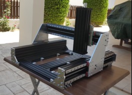
Sphinx 55 on MGN12 linear rails

Discussion in 'CNC Mills/Routers' started by SORIN ILIESCU, Sep 2, 2019.

  1. SORIN ILIESCU

    Builder

    Joined:
    Jun 12, 2019
    Messages:
    11
    Likes Received:
    55
    SORIN ILIESCU published a new build:

    Read more about this build...
     
    marspeed, Clark222, nythil and 2 others like this.
  2. Corey Corbin

    Corey Corbin Well-Known
    Builder

    Joined:
    Feb 27, 2016
    Messages:
    135
    Likes Received:
    62
    Ok sorry for the edit of my post, But I am interested in this setup. I have a sphinx half built and I would like the switch gears and follow your idea on the rails, So I have a couple of question. I would be interested in buying a set of your gantry plates would they be available from Mr laidlaw or a dxf file? And you used the standard end plates for the sphinx on the axis with 2 motors? And how is the setup with lead screw and the Anti backlash block? Was there a spacer? Thanks!
     
    #2 Corey Corbin, Sep 4, 2019
    Last edited: Sep 5, 2019
    SORIN ILIESCU likes this.
  3. ballen

    ballen New
    Builder

    Joined:
    Jul 20, 2019
    Messages:
    1
    Likes Received:
    1
    I am also super interested in this build! I would also like the dxf of the plates if you are willing. I am trying to figure out how/if I can fit ball screw into C beam or atleast T12 leadscrew. I have T8 on a workbee now and they seem flimsy.
     
    SORIN ILIESCU likes this.
  4. HuguesP

    HuguesP Well-Known
    Builder

    Joined:
    Jan 14, 2018
    Messages:
    30
    Likes Received:
    44
    My good, this machine is so sexy, i I had to do it again I would do mine like this.
    Do you think it could handle a 1.5kw spindle and mill Aluminium?
     
    EFFIEBABY1984 and SORIN ILIESCU like this.
  5. SORIN ILIESCU

    Builder

    Joined:
    Jun 12, 2019
    Messages:
    11
    Likes Received:
    55
    to be honest, I can’t see why it should not being able to handle it. But in December I will give it a try
     
  6. SORIN ILIESCU

    Builder

    Joined:
    Jun 12, 2019
    Messages:
    11
    Likes Received:
    55
    Chris designed and machined the plates for me, and I am sure that he will list the complete plates kit in his EBay store soon. As about the DXF files, you should talk with him about it. For the anti backlash nut/lead screw, I used a 3D printed spacer, using a STL file that Chris also provided.
     
    clementz likes this.
  7. SORIN ILIESCU

    Builder

    Joined:
    Jun 12, 2019
    Messages:
    11
    Likes Received:
    55
    I don’t have any DXF files, mate, I had the plates kit designed and machines by Chris Laidlaw
     
  8. Corey Corbin

    Corey Corbin Well-Known
    Builder

    Joined:
    Feb 27, 2016
    Messages:
    135
    Likes Received:
    62
    Awesome! I was hoping that was the case. I'll keep a eye on his Ebay store. Thanks for sharing your build!
     
    SORIN ILIESCU likes this.
  9. SORIN ILIESCU

    Builder

    Joined:
    Jun 12, 2019
    Messages:
    11
    Likes Received:
    55
  10. SORIN ILIESCU

    Builder

    Joined:
    Jun 12, 2019
    Messages:
    11
    Likes Received:
    55
  11. Chris Laidlaw

    Chris Laidlaw Well-Known
    Builder

    Joined:
    Mar 1, 2014
    Messages:
    77
    Likes Received:
    27
    Also, they are 10% off (the fee Ebay charges me) if you buy directly from me... [email protected]
     
  12. Andreas Bockert

    Andreas Bockert Well-Known
    Builder

    Joined:
    Oct 1, 2017
    Messages:
    142
    Likes Received:
    78
    Chris does great work and a really friendly guy.

    Did you just screw the rails to the to the c beams? When I looked at doing something similar I seem to recall that base of the rails wasn’t much larger then the the gap of the c beam. (At the top of the chamfer if this makes sense)

    I also like the reversed z axis.
     
    SORIN ILIESCU likes this.
  13. SORIN ILIESCU

    Builder

    Joined:
    Jun 12, 2019
    Messages:
    11
    Likes Received:
    55
    Yes, the rails are mounted with M3 screws, 8 mm length and with M3 T-Nuts, straight on top of the C -Beam. To be honest I had no issues doing that, except for the fact that I needed in total 140 M3 8mm screws and 140 M3 T-Nuts. To roughly center the rails on the C-Beam I used 3D printed spacers found at MGN12 Alignment Block by snicker and later I fine tuned the position of the rails using a dial indicator and a magnetic base, something similar to this item https://www.amazon.de/Flexible-Magn...&s=gateway&sprefix=Dial+,aps,214&sr=8-20&th=1
     
    Rick 2.0 likes this.
  14. SORIN ILIESCU

    Builder

    Joined:
    Jun 12, 2019
    Messages:
    11
    Likes Received:
    55
    Chris is a .... sweetheart, and the idea to reverse the Z axis comes from him as well. Great person, excellent machinist and very inventive.
     
  15. Andreas Bockert

    Andreas Bockert Well-Known
    Builder

    Joined:
    Oct 1, 2017
    Messages:
    142
    Likes Received:
    78
    Cool. My concern is that the top opening of the c beam is about 9mm and this only leaves about 1.5mm on each side for the rail to have contact with the c beam. Perhaps this is plenty enough for it to be strong, I’m not a mechanical engineer.

    I was considering milling plates to mount the rails to but it’s a lot of plates to mill and a lot of holes to tap.

    /Andreas
     
    SORIN ILIESCU likes this.
  16. SORIN ILIESCU

    Builder

    Joined:
    Jun 12, 2019
    Messages:
    11
    Likes Received:
    55
    I understand your point, but until now I got no signs of weakness from the linear rails assembly. I cutt through marine plywood at 4mm depth of cut, by mistake, and the machine didn’t complained at all.
    But there is always the option to go with MGN15, or even bigger, if you think that the MGN12 is not enough wide
     
  17. daveo

    daveo New
    Builder

    Joined:
    May 8, 2016
    Messages:
    6
    Likes Received:
    0
    Hi
    I am also looking at this build but would like to extend it to 1000mm x 1000mm with the linear rail kit and the 1.5kw spindle,just wondering if the 8mm lead screws will take it?
     
  18. daveo

    daveo New
    Builder

    Joined:
    May 8, 2016
    Messages:
    6
    Likes Received:
    0
    does any one have the parts list so i can work out the extrusion
    thanks dave
     
  19. MrGoodCat

    MrGoodCat New
    Builder

    Joined:
    Feb 22, 2015
    Messages:
    1
    Likes Received:
    0
    this is an awesome build!

    I accidentally tripped and fell in a rabbit hole when looking to upgrade my c-beam machine x-axis. I am now planning on building a sphinx style machine and really like this linear rail setup. I am new to linear rails in general and am a bit overwhelmed by all the brands, sources, china knock-offs, etc.

    can anyone suggest an affordable/reputable source for these mgn12 rails and bearing blocks? seems like options range from $400 to $1000+ depending on brand alone. what brand do people use or suggest for hobby-esque cnc builds?

    also, do the bearing blocks seal well enough to keep dust out? I plan on cutting mainly wood with this cnc router. my current c-beam machine is a dust generator and when attempting to rig up a dust shoe I quickly learned the x-axis was flimsy, hence the trip down the rabbit hole...
     
  20. Giarc

    Giarc OpenBuilds Team
    Staff Member Moderator Builder Resident Builder

    Joined:
    Jan 24, 2015
    Messages:
    3,008
    Likes Received:
    1,676
    A couple people have converted their workbees to linear rails with these from Amazon. They are 15 mm but 12 mm are available as well. I bought them recently because I plan to modify my custom build CNC router.
     
  21. Raul Arrabal

    Builder

    Joined:
    Oct 27, 2019
    Messages:
    1
    Likes Received:
    0
    Nice work !!!, im really interested in make the same build, i just looking arround and i like too much, ¿dou you have the full part list?, ¿did you try to cut aluminium yet?
     
  22. Alidi-ntg

    Alidi-ntg New
    Builder

    Joined:
    Jan 14, 2020
    Messages:
    1
    Likes Received:
    0
    Hi Chris,

    two questions.
    Which is the size of the real working area ? X / Y / Z -> 450x450mmx150mm ?
    Can you provide to me the stocklist for this machine ?

    Greetings from Germany

    Alidi-ntg
     
  23. Glenn71

    Glenn71 New
    Builder

    Joined:
    Dec 7, 2019
    Messages:
    1
    Likes Received:
    0
    I'm also interested in this build. Is there any drawing of this build that is for sale?
    I have aluminium profiles from an industrial machine that I was going to use but it's not the same as you have.
     
  24. msaeger

    msaeger New
    Builder

    Joined:
    Sep 23, 2015
    Messages:
    32
    Likes Received:
    1
    How large of diameter screws do you think you could fit? I want to make something 1500x1500 so I think I should use larger ball screws.
     
  25. Jared Piepmeier

    Builder

    Joined:
    May 18, 2020
    Messages:
    1
    Likes Received:
    1
    Where can I find the CADD files for this build?
     
    James_Hopkins likes this.
  26. NeeqOne

    NeeqOne Well-Known
    Builder

    Joined:
    Mar 3, 2018
    Messages:
    46
    Likes Received:
    27
    Are four linear rails really necessary for the Y axis? I believe a lot of money can be saved for the same performance by going with a single linear rail with dual carriage on each of the Y axis.
     
  27. Corey Corbin

    Corey Corbin Well-Known
    Builder

    Joined:
    Feb 27, 2016
    Messages:
    135
    Likes Received:
    62
    Well more rigidity and symmetrical load on 2 rails and 4 blocks might give the impression each rail is more efficient at 50% of the load compared to one rail holding 100% of the load. Kind of like having 2 pair of the same work boots alternate every other day the 2 last longer then the one pair. Hey if you happen to try it let us know I would be interested to your solution how you mounted them. And see performance on one rail per side. Would mount it on top or on side? Personally I have a bad habit of doubling everything anyways.
     
  28. Giarc

    Giarc OpenBuilds Team
    Staff Member Moderator Builder Resident Builder

    Joined:
    Jan 24, 2015
    Messages:
    3,008
    Likes Received:
    1,676
    I have doubled mine as well. I was making progress yesterday until I dropped one of my Y axis ends with 4 blocks mounted on it on the concrete floor. Then I spent the next two hours trying to find all the ball bearings that went flying. :banghead:
     
  29. Matthiu

    Matthiu New
    Builder

    Joined:
    Jun 13, 2020
    Messages:
    2
    Likes Received:
    0
    Maybe someone can help me. I bought the kit from Chris and got my rails in but I'm confused by the several thick blocks that came with the plates. What do I do with them?
     
  30. Corey Corbin

    Corey Corbin Well-Known
    Builder

    Joined:
    Feb 27, 2016
    Messages:
    135
    Likes Received:
    62
    @Giarc - Wow! Did you get them all? I was wondering how hard it is to place the ball bearings back in. I have order my self for the Z and Y axis linear rails. Have a plan to convert to linear rails too. Except I am going to draw up and cut my own plates. Sphinx style and hoping my little 500w spindle last thru all these plates.

    @Matthiu - I am thinking those are the blocks the will bolt to the plate as a stand off for the lead screw Anti Blacklash nut block. Block with 2 5mm holes and a slot in middle.
     

Share This Page

  1. This site uses cookies to help personalise content, tailor your experience and to keep you logged in if you register.
    By continuing to use this site, you are consenting to our use of cookies.
    Dismiss Notice