Welcome to Our Community

Some features disabled for guests. Register Today.

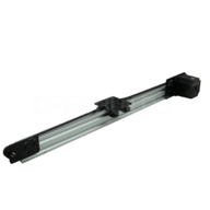
V-Slot™ Nema 23 Linear Actuator Build (Belt Driven)

Discussion in 'Other Builds' started by Mark Carew, Nov 14, 2018.

  1. Mark Carew

    Mark Carew OpenBuilds Team
    Staff Member Moderator Builder Resident Builder

    Joined:
    Jun 28, 2013
    Messages:
    2,763
    Likes Received:
    2,448
    Mark Carew published a new build:

    Read more about this build...
     
    GrayUK and Peter Van Der Walt like this.
  2. P01

    P01 New
    Builder

    Joined:
    Nov 12, 2018
    Messages:
    15
    Likes Received:
    2
    Hello builders!

    I wold like to use this build (1500mm with NEMA 23) in a research lab.
    I have no experience with linear actuators, so could you please advise me if this design fulfils my requirements.

    The idea is to mount a small monitor (or tablet) on the actuator’s plate and move it in
    a cyclic patterns (constant speed, step displacement, sine displacement, …):

    upload_2018-11-18_18-26-32.png upload_2018-11-18_18-26-48.png

    My questions:
    1. Is this design rugged enough to handle max. 2kg load at max. speed 1m/s?
    2. I would like to accelerate from 0m/s to 1m/s in shortest distance possible. What would be the distance? The same question for slowing down from 1m/s to 0m/s.
    3. How precise would be the positioning of 2kg load? For example, moving it 1000 millimetres at max. speed 1 m/s.
    4. What noise shell I expect from linear actuator with the bundled NEMA 23 (in dBA or description)?
    Thank you for any advice!
     
    #2 P01, Nov 18, 2018
    Last edited: Nov 18, 2018
  3. Peter Van Der Walt

    Peter Van Der Walt OpenBuilds Team
    Staff Member Moderator Builder Resident Builder

    Joined:
    Mar 1, 2017
    Messages:
    15,307
    Likes Received:
    4,361
    Hi P01

    1) It's hard to quantify the Acceleration without trial-and-error (So my 1500mm/s2 guess may be way off, but experience and gut feel, says its close for our NEMA23s and a 2KG load (Not a lightweight at all)
    2) Punching those numbers into the Prusa Acceleration calculator (RepRap Calculator - Prusa Printers) Gives me (See below)
    accel.PNG

    ie, just over 300mm acceleration and 300mm deceleration (leaving less than 900mm of travel at 1m/s)

    This basic acceleration calculation assumes that the motor and driver can keep up though, so:
    3) The next point to think about is the driving characteristics. Here there are too many variables to give an exact Yes/No answer (So if time/budget allows you might want to try this hand-on to experiment with your actual use-case, conditions and setups):
    3.1) The required Motor RPM can be calculated from the Pulley diameter and selected Microstepping
    3.2) Then three different components come into play: Stepper motor, Stepper Driver and Control electronics. All three has to be able to achieve the required max RPM / acceleration (As mentioned above). In this case, keep in mind there are hundreds of steps per mm * 1000mm = couple hundred KHZ step rate - so even your consideration of controller (Grbl can reach between 50-100khz - so probably need something faster) comes into play.
    4) This is probably achievable, but not likely to be easy unless you take slow accelerations or limit the maximum speed a little more

    Hope that helps!
     
    Mark Carew likes this.
  4. P01

    P01 New
    Builder

    Joined:
    Nov 12, 2018
    Messages:
    15
    Likes Received:
    2
    Thank you for the reply. I suppose, it must be quite difficult to predict all the properties of the linear actuator in a specific use-case situation, but reading your answers, I think that it is worth to give it a try. If I finally build one, I will let you know the results. Thank you again.
     
    Mark Carew likes this.
  5. dung pham

    dung pham New
    Builder

    Joined:
    Dec 1, 2018
    Messages:
    1
    Likes Received:
    0
    Hi, I want to build exactly this v-slot nema 2 linear actuator belt driven, and can move from 0 to 40" or 60". I see the list of parts . In stepper motor, it shows "Note: Stepper motors require special driver circuits to drive them. These drive circuits allow you to step the motor precisely to any position.". Can you please let me know what stepper motor and drive I need to buy and anything else I need to buy to complete this project.
    Qty Part Name Part Link Comments
    4 Low Profile Screws - 25mm Low Profile Screws M5 (10 Pack) SKU 20 - Sold in Packs - You will need 4 Singles
    6 Low Profile Screws - 8mm Low Profile Screws M5 (10 Pack) SKU 946 - Sold in Packs - You will need 4 Singles
    2 Aluminum Spacer - 6mm http://openbuildspartstore.com/aluminum-spacers/ SKU 90
    1 Aluminum Spacer - 3mm http://openbuildspartstore.com/aluminum-spacers/ SKU 175
    3 Double Tee Nuts http://openbuildspartstore.com/double-tee-nut/ SKU 60
    1 3GT (GT2-3M) Timing Pulley - 20 Tooth https://openbuildspartstore.com/3gt-timing-pulley-20-tooth/ SKU 830
    2 Eccentric Spacers - 6mm http://openbuildspartstore.com/eccentric-spacer/ SKU 226
    4 Delrin Solid V Wheel Kit http://openbuildspartstore.com/solid-v-wheel-kit/ SKU 480
    1 Smooth Idler Pulley Kit http://openbuildspartstore.com/smooth-idler-pulley-wheel-... SKU 550
    1 Idler Pulley Plate http://openbuildspartstore.com/idler-pulley-plate/ SKU 570
    1 Motor Mount Plate for Nema 23 Stepper Motor https://openbuildspartstore.com/motor-mount-plate-nema-23... SKU 910
    4 Cable Ties - 4" http://openbuildspartstore.com/cable-ties-10-pack/ SKU 675 - Sold in Packs - You will need 4 Singles
    4 Low Profile Screws - 15mm https://openbuildspartstore.com/low-profile-screws-m5-10-... SKU 922
    1 V-Slot Gantry Plate (20mm) http://openbuildspartstore.com/v-slot-gantry-plates/ SKU 935
    1 3GT (GT2-3M) Timing Belt - By the Foot https://openbuildspartstore.com/3gt-gt2-3m-timing-belt-by... Length Varies - 3' for 250mm, 4' for 500mm, 7' for 1000mm, 11' for 1500mm
    1 Nema 23 Stepper Motor https://openbuildspartstore.com/nema-23-stepper-motor/ SKU 518
    1 V-Slot® Linear Rail http://openbuildspartstore.com/v-slot-linear-rail/ Varies
    4 Nylon Insert Hex Locknut - M5 (10 Pack) https://openbuildspartstore.com/nylon-insert-hex-locknut-... SKU 10-pack
     
  6. Mark Carew

    Mark Carew OpenBuilds Team
    Staff Member Moderator Builder Resident Builder

    Joined:
    Jun 28, 2013
    Messages:
    2,763
    Likes Received:
    2,448
  7. P01

    P01 New
    Builder

    Joined:
    Nov 12, 2018
    Messages:
    15
    Likes Received:
    2
    Hello, what would be the best way to mount a rotary encoder on the linear actuator? I have two reasons to do it:
    1. To know the exact position of the plate/load, to make sure that the load is able to keep up with programmed acceleration, that there is no slipping of the belt, etc.
    2. As a security measure: to detect if the plate/load is blocked (unable to move).
    So, to mount the rotary encoder (I hope I can include the link):
    https://www.amazon.com/Aideepen-Enc...e=UTF8&qid=1544313625&sr=8-5&keywords=encoder

    I can think of a few options:
    1. To mount it directly on the plate and use some kind of a wheel mounted on the encoder’s shaft to make it spin in contact with the V-slot rail.
    2. To mount it on the V-slot rail (close to the motor), and put a 3GT (GT2-3M) Timing Pulley on the encoder's shaft to make it spin in contact with the belt.
    3. To mount it on the V-slot rail and substitute a Smooth Idler Pulley with the rotary encoder.
    Which option would be the most recommended? Are there any parts in openbuildspartstore to make the mount easy?
    Thank you.
     
  8. Rick 2.0

    Rick 2.0 OpenBuilds Team
    Staff Member Moderator Builder Resident Builder

    Joined:
    Dec 20, 2013
    Messages:
    2,899
    Likes Received:
    1,556
    I'd be inclined to find a dual shaft stepper and mount it on the back.
     
  9. P01

    P01 New
    Builder

    Joined:
    Nov 12, 2018
    Messages:
    15
    Likes Received:
    2
    Hello Rick 2.0, thank you for the reply. I have not considered the dual shaft stepper mount because, I think, I should be watching the plate/load or at least the belt movement. I will be using the linear actuator in a way that differ from typical cnc use-case:

    1. To move the load between 1kg and 2kg with maximum acceleration that the high torque stepper motor allows.
    2. Try to control the trajectory (I mean acceleration and speed) of the load as precise as possible (to replicate programmed patterns). At least I have to know exact position of the load at every moment to take into account its real trajectory.

    If I mount the encoder on the stepper’s shaft, I will not be able to detect the belt slipping (I do not know if it is real issue or just my imagination).
     
  10. Rick 2.0

    Rick 2.0 OpenBuilds Team
    Staff Member Moderator Builder Resident Builder

    Joined:
    Dec 20, 2013
    Messages:
    2,899
    Likes Received:
    1,556
    In that case, due to the forces you'll likely be experiencing at each end, I'd pick up a matching Idler Pulley Plate for the opposing side of the far end and drill out the axle hole both sides for a pair of flanged bearings. Then just use a regular pulley fixed on an axle rod with one end protruding outside the bearings far enough to attach the encoder to.
     
  11. Tommy Carney

    Builder

    Joined:
    Dec 12, 2018
    Messages:
    3
    Likes Received:
    0
    I am using a v-slot nema 23 1500mm linear actuator to run a powdercoat gun back and forth with a travel distance of about 1 meter. I purchased two of these actuators because I have two guns that need this movement.

    I wanted to use the CNC xPRO controller to control both actuators. I thought I could hook up one actuator to the x-axis and one to the y-axis. Then I could use the OpenBuilds CAM to draw a diagonal line through the x and y axis, and thus would have matching movement in both actuators.

    I basically wanted the actuators to run back and forth through this diagonal line continuously with a change in speed at one point. Also, I wanted one directional change on the diagonal line to be slower than the other.

    I am having trouble getting this done in the software. Is it possible to do this sort of thing with CNC software?
     
  12. P01

    P01 New
    Builder

    Joined:
    Nov 12, 2018
    Messages:
    15
    Likes Received:
    2
    Hi Rick 2.0, thank you for the suggestion but I have a difficulty to visualize your solution. Do you mean to replace the original Iddler Pulley Plate (and Smooth Idler Pulley) with the modified one that you suggest? If it is not too much to ask, could you please sketch it (by hand on a piece of paper or whatever) to get a better idea? Thank you a lot.
     
  13. Peter Van Der Walt

    Peter Van Der Walt OpenBuilds Team
    Staff Member Moderator Builder Resident Builder

    Joined:
    Mar 1, 2017
    Messages:
    15,307
    Likes Received:
    4,361
    Might be easier with hand written gcode. Couple simple G1 moves
     
  14. Rick 2.0

    Rick 2.0 OpenBuilds Team
    Staff Member Moderator Builder Resident Builder

    Joined:
    Dec 20, 2013
    Messages:
    2,899
    Likes Received:
    1,556
    Concept shown and Sketchup file attached. (Note: Sketchup file not fully detailed but sufficient to get the idea.)

    Encoder attachment 2.jpg Encoder attachment.jpg

    Belt drives pulley, pulley drives shaft and encoder attaches to shaft extension. I'll leave the encoder mount and attachment to you. You may also need some shim washers to keep the pulley centered.
     

    Attached Files:

    P01 likes this.
  15. P01

    P01 New
    Builder

    Joined:
    Nov 12, 2018
    Messages:
    15
    Likes Received:
    2
    Rick 2.0, thank you very much, now it is clear for me.
     
  16. Tommy Carney

    Builder

    Joined:
    Dec 12, 2018
    Messages:
    3
    Likes Received:
    0
    I messed around with the G code, but wasn't able to find a way to program a loop with grbl. I need the linear actuators to run back and forth, until the powder coating job is complete. Will I have to program the xPro with arduino, or is there something I am missing?
     
  17. Peter Van Der Walt

    Peter Van Der Walt OpenBuilds Team
    Staff Member Moderator Builder Resident Builder

    Joined:
    Mar 1, 2017
    Messages:
    15,307
    Likes Received:
    4,361
    Surely its a set area? (copy paste, not infinate loop?)

    Otherwise go for it - Arduino for the win, the Xpro is basically an Uno :)
     
  18. Tommy Carney

    Builder

    Joined:
    Dec 12, 2018
    Messages:
    3
    Likes Received:
    0
    Sorry for my ignorance on coding. When I hit the start button, I basically need the linear actuator to run back and forth continuously (maybe for 6 hours or so) until I hit the stop button. I looked up the g code supported on grbl and couldn't find a command which would allow movement to repeat continuously until I pressed stop. Of course, I might be mistaken.
     
  19. Peter Van Der Walt

    Peter Van Der Walt OpenBuilds Team
    Staff Member Moderator Builder Resident Builder

    Joined:
    Mar 1, 2017
    Messages:
    15,307
    Likes Received:
    4,361
    Correct, no canned cycles. Custom arduino code it is then :)
     
  20. Ronny Roos

    Builder

    Joined:
    Mar 8, 2019
    Messages:
    5
    Likes Received:
    0
    Hi All!

    I’m in the starting phases of a project where I need to move approximately 5kg of weight over 300mm with speeds upwards of 600mm.

    I intend to drive this with the ODrive, which is basically a powerful hobby motor with an encoder on it, I figure this should give me the power and speed needed.
    However, I have concerns that the belt would slip due to weight and resistance. Should I be looking at leadscrews (according to my calculations there would be too much whip in them at these speeds and distances)?
     
  21. Giarc

    Giarc OpenBuilds Team
    Staff Member Moderator Builder Resident Builder

    Joined:
    Jan 24, 2015
    Messages:
    3,035
    Likes Received:
    1,695
    I do not know why you would get too much whip at only 300 mm length and 600 mm/minute. Or did you mean 600 mm/sec. :eek: Anyways, I routinely run my CNC router at 3000 mm/min and have run it at 8000mm/min just for kicks once. My x axis length is 840 mm with a 3/8 inch 4 start (1/2 inch per rotation) lead screw. The router is a Makita and it weighs 3.9 pounds.
     
    Mark Carew likes this.
  22. Ronny Roos

    Builder

    Joined:
    Mar 8, 2019
    Messages:
    5
    Likes Received:
    0
    600mm/s sorry! Forgot the unit!
     
  23. Giarc

    Giarc OpenBuilds Team
    Staff Member Moderator Builder Resident Builder

    Joined:
    Jan 24, 2015
    Messages:
    3,035
    Likes Received:
    1,695
    That's OK. I misread your 5 KGs as 5 pounds. But still, it is such a short distance, I do not think whip will be a problem. If still concerned, you can get 1/2"-10 5 start precision acme screws from McMaster Carr. I use them on my 1500 mm Y axis, and as I mentioned before, had them going at 8000mm/min without much whip. With the weight of both the X axis gantry, the z axis and spindle, I must be easily near 5 kg if not more.
     
  24. P01

    P01 New
    Builder

    Joined:
    Nov 12, 2018
    Messages:
    15
    Likes Received:
    2
    This question is about motor selection for the V-Slot NEMA 23 Linear Actuator (Belt Driven) and about accuracy with load mouted on the plate.

    Does it make any sense to use the high torque (345 oz*in) NEMA 23 motor instead of the standard NEMA 23 (175 oz*in)?

    I am asking this question because:
    1. V-Slot NEMA 23 Linear Actuator (Belt Driven) specification says:
      • Max Force: 7.5lb (33N).
    2. The Actuator Test Specs specifies:
      • Result: Belt skips at approximately 7.5lb (33N)
    If the result was that the motor stalls at 33N I could obtain more force by using stronger motor, but it says “belt skips”.

    The actuator uses 3GT (GT2-3M) Timing Pulley with diameter 18.3mm, so the standard NEMA 23 motor (175 oz*in = 1.24Nm) can produce F = 1240 / (18.3 / 2) = 135.5N. This force is much higher than 33N when the belt skips, so using stronger motor makes no sense to me.

    Maybe, if I wanted to control the motor at high speed the additional torque would be advantageous.

    Are my conclusions correct?
    Is there any way to prevent the belt skipping?

    What accuracy shell I expect with 1kg load mounted on the plate and moving it between 0 and 1000mm?

    In the document Actuator Test Specs, page 3, test 4, target distance 60mm was measured 61.17mm (max error 1.17mm) without load. So, what positioning accuracy (max error) shell I expect with 1kg load and travel distance between 0 and 1000mm (at slow and high speeds)?

    Thank you.
     
    #24 P01, Nov 11, 2019
    Last edited: Nov 13, 2019
  25. Rob Stehlik

    Builder

    Joined:
    Apr 20, 2015
    Messages:
    12
    Likes Received:
    73
    Sorry for the late reply, but I'm not really involved with open builds any more. You are right that the stronger motor with the belt drive doesn't make much sense. The limitation is in the size of belt and pulleys. A 5mm pitch belt would be much better, but this is not really supported by open builds. If you are concerned about the belt skipping, consider using a screw instead. All of the testing was done under no load conditions, so I can't comment on your specific scenario with a 1kg mass. That doesn't seem too high, but if you are trying to move really fast, the belt will be a limiting factor.
     
  26. P01

    P01 New
    Builder

    Joined:
    Nov 12, 2018
    Messages:
    15
    Likes Received:
    2
    Rob, thank you for the reply.
     
  27. Evan Leavitt

    Builder

    Joined:
    Aug 10, 2014
    Messages:
    14
    Likes Received:
    4
    I just received my kit and have a cheap amazon stepper motor controller that I'll be using till I work out more details. I was wondering is there is an Arduino project out there already for linear actuator or something similar? Thanks!
     
  28. Giarc

    Giarc OpenBuilds Team
    Staff Member Moderator Builder Resident Builder

    Joined:
    Jan 24, 2015
    Messages:
    3,035
    Likes Received:
    1,695
    Evan Leavitt likes this.
  29. Evan Leavitt

    Builder

    Joined:
    Aug 10, 2014
    Messages:
    14
    Likes Received:
    4
  30. Bret Wills

    Builder

    Joined:
    Aug 7, 2022
    Messages:
    2
    Likes Received:
    0
    Hoping this is the right place to ask this question. I built this project with the NEMA 23. All my other motor are NEMA 17s from Steppermotor online and are wired Blue|Red|Green|Black. The pre-wired terminal block included (which is very nice indeed, and I'm replacing my current build with these) is Red|Blue|Green|Yellow. I'm wondering if I ignore that order and go with what I'm doing when hooking it up to my stepper drivers which are TB6600's? TIA
     

Share This Page

  1. This site uses cookies to help personalise content, tailor your experience and to keep you logged in if you register.
    By continuing to use this site, you are consenting to our use of cookies.
    Dismiss Notice