Welcome to Our Community

Some features disabled for guests. Register Today.

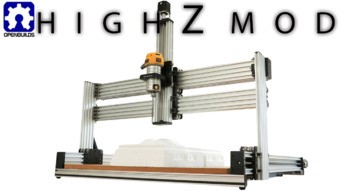
High Z Mod for Lead CNC

Discussion in 'CNC Mills/Routers' started by Mark Carew, Oct 11, 2019.

  1. Rick 2.0

    Rick 2.0 OpenBuilds Team
    Staff Member Moderator Builder Resident Builder

    Joined:
    Dec 20, 2013
    Messages:
    2,893
    Likes Received:
    1,552
    Are you referring to a Z-axis configuration similar to the sketch about 3 posts up? If so, you have all the parts necessary.
     
  2. ClaudeJER

    ClaudeJER Well-Known
    Builder

    Joined:
    Oct 2, 2018
    Messages:
    39
    Likes Received:
    27
    I'll have another look at it using the Workbee Z setup as guide.
    The xl plates configuration is slightly different with wheels mounted on the front and back in respect to the X axis.
    Do you have a machine setup in that way?
    I can't see how I can get the Z beam mounted the same way as the workbee with the hardware I have.
    I think I am missing an xl plate or
    I build the X axis carriage with the two wheels between the xl plates and use extra long screws and eccentric adjusters to have four wheels in the front to mount the Z beam.
    In any of these option, I don't think I have the required parts!
     
    #32 ClaudeJER, Mar 10, 2020
    Last edited: Mar 10, 2020
  3. stuart wallace

    Builder

    Joined:
    Jul 28, 2019
    Messages:
    57
    Likes Received:
    6
    please post photos if you accomplish this. My coffee hasn’t kicked in yet but I know that I’ve had a similar thought as your original post about this. Cheers
     
  4. ClaudeJER

    ClaudeJER Well-Known
    Builder

    Joined:
    Oct 2, 2018
    Messages:
    39
    Likes Received:
    27
    Rick 2.0,
    Before I take my machine apart just to have a look,
    Using the LEAD xl plates, is it possible to have four wheels mounted in the front of the X axis with the required eccentric adjusters to have the Z beam free to move up and down
    instead of using an extra xl plate mounted back to back to the X axis?
     
  5. Rick 2.0

    Rick 2.0 OpenBuilds Team
    Staff Member Moderator Builder Resident Builder

    Joined:
    Dec 20, 2013
    Messages:
    2,893
    Likes Received:
    1,552
    Can’t offer a really good explanation right now as I’m at work working on my phone but the only reason for the plate on the backside of the Z-axis is to access the drive screw. In the sketch above the upper rail only has a plate on the front side which is set back to back with another XL plate which the Z-axis rides in. Note, it is best if the lower rail is the drive rail in this system. The upper plate has less force on it so it doesn’t matter if it has only 4 wheels and no back plate.
     
  6. ClaudeJER

    ClaudeJER Well-Known
    Builder

    Joined:
    Oct 2, 2018
    Messages:
    39
    Likes Received:
    27
    I think I just answered my own question about four extra wheels mounted in front of the X axis carriage.
    I don't think it is possible for two axis to share the same screws for both the X and Z axis eccentric adjustment, the position at which both axis adjustment would meet and be happy would be so small because they share the same screws.
    I don't think there is any other way of accomplishing this without the addition of one more xl plate and associated wheels and eccentric.
     
  7. Rick 2.0

    Rick 2.0 OpenBuilds Team
    Staff Member Moderator Builder Resident Builder

    Joined:
    Dec 20, 2013
    Messages:
    2,893
    Likes Received:
    1,552
    It can be done with a minimum of 5 plates which should be exactly how many you have.
     
  8. ClaudeJER

    ClaudeJER Well-Known
    Builder

    Joined:
    Oct 2, 2018
    Messages:
    39
    Likes Received:
    27
    I’m looking forward to seeing how.
    Thanks.
     
  9. Rick 2.0

    Rick 2.0 OpenBuilds Team
    Staff Member Moderator Builder Resident Builder

    Joined:
    Dec 20, 2013
    Messages:
    2,893
    Likes Received:
    1,552
    5 plates as shown:
    5 Plates.jpg
    And with the Z-axis plates turned 90 degrees to the X-axis plates they connect easily with screws through open holes into threaded holes. The X-axis lead screw nut will be attached to the bottom plate in the rear and the Z-axis lead screw nut can be attached to either of the front plates.
     
    Giarc and Batcrave like this.
  10. ClaudeJER

    ClaudeJER Well-Known
    Builder

    Joined:
    Oct 2, 2018
    Messages:
    39
    Likes Received:
    27
    Thanks Rick,
    I'll do that tonight but somehow, I vaguely remember thinking of mounting it this way but didn't have the required parts.
    Carefully looking at your drawing above, I just noticed that the top carriage has been reduced to one plate from two and that's where the needed extra plate comes from.
    I will follow up with pictures in a while.
    C.
     
    #40 ClaudeJER, Mar 10, 2020
    Last edited: Mar 10, 2020
    stuart wallace likes this.
  11. ClaudeJER

    ClaudeJER Well-Known
    Builder

    Joined:
    Oct 2, 2018
    Messages:
    39
    Likes Received:
    27
    Got it done and it is much better this way.
    Here's a few pictures. IMG_1237.JPG IMG_1238.JPG IMG_1239.JPG
     
    Leahy, Giarc, Batcrave and 1 other person like this.
  12. plasma

    plasma New
    Builder

    Joined:
    Jul 30, 2015
    Messages:
    9
    Likes Received:
    2
    Custom upgraded lead CNC.
     

    Attached Files:

    Batcrave likes this.
  13. plasma

    plasma New
    Builder

    Joined:
    Jul 30, 2015
    Messages:
    9
    Likes Received:
    2
    Few more.
     

    Attached Files:

    Batcrave likes this.
  14. Batcrave

    Batcrave Journeyman
    Builder

    Joined:
    Apr 20, 2018
    Messages:
    361
    Likes Received:
    166
    Is that one of the square Chinese air-cooled spindles I see there?

    How's it working out? They looked great for mountability, but I was too taken with the idea of a water-cooled model (which, granted, has worked out lovely, but I still find myself staring wistfully at the square ones from time to time).

    Spindle aside, those are some impressive mods. What all else did you do? It looks like you doubled up the C-beams on the sides & ran linear rails instead of the wheels, a new bed, and are those ballscrews? I can't tell what you used for those brown endplates holding the C-beams together, though.

    Also, what's that keyboard? I've been dying for something better to use as a controller, ever since giving up Mach 3 and the fantastic joypad plugin for a PS3 controller.

    One way or another, that's one impressive machine.

    -Bats
    (of course, now I'm feeling terribly jealous, and twice as frustrated about mine being constantly out of commission instead of growing and mutating *sniffle*)
     
  15. Giarc

    Giarc OpenBuilds Team
    Staff Member Moderator Builder Resident Builder

    Joined:
    Jan 24, 2015
    Messages:
    3,017
    Likes Received:
    1,682
    That looks really cool, Plasma. I am in the midst of working out the fittings before cutting more plates. Somehow I had a bunch of holes off by 0.3mm last night while trying to line stuff up in Fusion 360. It drove me nuts until nearly 2 am until I realized what happened. My LEAD high z kit is on the way soon. I already had my linear rails from nearly a year ago. Time flies. I have some 1/8 inch aluminum diamond plate I hope to use across the front of the two Cbeams to bond them together. If that falls through, I will put a 3/16" aluminum plate.
    Untitled.png Untitled2.png
     
    plasma and Batcrave like this.
  16. plasma

    plasma New
    Builder

    Joined:
    Jul 30, 2015
    Messages:
    9
    Likes Received:
    2
    Thanks Batcrave.

    All beams were doubled down for rigidity. Lead screws were upgraded to 12mm on both x and y axis. So were the steppers. They were upgraded to Nema 34 closed loop 8.5N.
    All the plates I milled on the lead CNC before the upgrade from 7000 aluminum for extra rigidity and then painted them metallic bronze.
    The motor is great. I have used it for about a year right now. It’s a workhorse. No issues. And very easy to trim in my configuration.

    The controller I use is Arduino uno connected to a intel Nuk running Linux.

    The keyboard is used in conjunction with Jason CNC to manually control the movement of the axis.


    Attached Files:

  17. plasma

    plasma New
    Builder

    Joined:
    Jul 30, 2015
    Messages:
    9
    Likes Received:
    2
     
  18. Batcrave

    Batcrave Journeyman
    Builder

    Joined:
    Apr 20, 2018
    Messages:
    361
    Likes Received:
    166
    I think your reply may have gotten lost somewhere, @plasma .
     
  19. darrepac

    darrepac New
    Builder

    Joined:
    Feb 28, 2017
    Messages:
    54
    Likes Received:
    9
    Hi Rick

    Any reason why this sketch (putting the router attached directly to the Z beam and make the whole Z beam move up and down) is not the default mounting option for the high Z mod?
    I do not see the benefit of the default mounting...
    thanks
     
  20. Rick 2.0

    Rick 2.0 OpenBuilds Team
    Staff Member Moderator Builder Resident Builder

    Joined:
    Dec 20, 2013
    Messages:
    2,893
    Likes Received:
    1,552
    Go back to the photo of where Mark is cutting the Hans Solo in Carbomite with a 4” bit in 4” foam. He only needs a little over 4” clear beneath the Z-axis beam to pull this off. With the router affixed to the axis beam and a 4” bit sticking down the axis beam has to start at 8” clear. While it makes no difference with foam keeping the X-axis as low as possible and the Z-axis projecting as little as possible makes a big difference when cutting hard materials. Jacking up the X-axis and reaching back down with the Z-axis only reduces the stiffness of the machine which reduces the quality of the cuts in hard materials. Truly a personal choice but I tend to stick with the fixed beam/moving router/low X-axis in my designs to keep the system as rigid as possible. Never know when you might be inclined to cut aluminum.
     
    Peter Van Der Walt likes this.
  21. Batcrave

    Batcrave Journeyman
    Builder

    Joined:
    Apr 20, 2018
    Messages:
    361
    Likes Received:
    166
    A subsidiary of the Hutt Farms Group responsible for their eponymously named competitor to Vegemite and Marmite, the Carbomite Company fell on hard times after Imperial health inspectors discovered traces of freelance Dutch import/export contractor Hans Solo in a palette bound for Tatooine onboard a transport belonging to Fett Trucking, Inc.

    I've been puzzling over this post of yours for a couple days now, Rick (err, the non-StarWarsy parts of it, mostly), and I was hoping you could clear up whatever I'm misunderstanding. The stock build may make perfect sense if you always cut 4" thick workpieces with 4" bits, but if you're ever going to use that same machine for shallower workpieces (say, a plate of some of that aluminum you mentioned) would it really be better to reach way down from the bottom of the fixed beam with a skinny little extended-reach bit (as the design seems to require) than to run the whole beam down and use a stubby bit?

    The stock configuration seems like it would be especially problematic when using 1/8" shank bits (I can get little 1/8" 10-90° engraving bits by the fistful, for example - and need them by the fistful due to the fragile points - but finding them with a 4" long 1/4" shank sounds a little more challenging and a lot more expensive.

    So am I just misunderstanding how one configuration or the other works here? Or are there some of those fancy mecheng numbers involved that always sail over my head?


    -Bats
    (any self-respecting bat should be able to catch just about anything flying overhead. I'm so ashamed)
     
  22. Rick 2.0

    Rick 2.0 OpenBuilds Team
    Staff Member Moderator Builder Resident Builder

    Joined:
    Dec 20, 2013
    Messages:
    2,893
    Likes Received:
    1,552
    Absolutely correct. And yes, otherwise it makes no sense. But then again...

    It really comes down to how you use your machine as there are decent arguments both ways. The lower you keep the X-axis the stiffer the machine and the stiffer the machine the better the cut in hard materials. If you aren't intending to cut metals though the fixed axis beam makes no sense. If you're looking to make 2" deep cuts into wood that is 6" thick by all means go with the moving axis beam.

    Of course not. Take the work to the bit, not the bit to the work. Build a 2" to 3" thick working platform for when you're cutting aluminum plate. Router projection will easily reach the material even with a stubby bit.

    Again, it really comes down to how you plan to use the machine. So to say which should be the default mode, that would imply that there is a default type of project that the system should be used on.
     
    Giarc and Peter Van Der Walt like this.
  23. JustinTime

    JustinTime Veteran
    Builder

    Joined:
    Dec 18, 2013
    Messages:
    784
    Likes Received:
    259
    That is exactly how I plan/ed to do it on my machine (that is in progress and will be finished as soon as Canada post decides to deliver my packages that they are holding on to for weeks) where the clearance to the build plate is about 5"
     
    outlaws42 likes this.
  24. outlaws42

    outlaws42 New
    Builder

    Joined:
    Oct 2, 2015
    Messages:
    12
    Likes Received:
    5
    Hey ClaudeJER

    I was thinking of changing mine around because of the same reason you stated earlier. I see you have more Z clearance then the standard machine. This looks to me like a much better configuration. Before I take mine apart I wanted make sure it is going to gain Z clearance from the standard height. How thick is your spoil board?
    Thanks
    Troy
     
    #54 outlaws42, Apr 21, 2020
    Last edited: Apr 21, 2020
  25. Giarc

    Giarc OpenBuilds Team
    Staff Member Moderator Builder Resident Builder

    Joined:
    Jan 24, 2015
    Messages:
    3,017
    Likes Received:
    1,682
    This is what I did to mill aluminum angle pieces for my CNC mod (High Z type LEAD mod) I am in the process of doing . It worked great.
    DSC_0173.JPG
    DSC_0176.JPG
     
    Rick 2.0 likes this.
  26. ClaudeJER

    ClaudeJER Well-Known
    Builder

    Joined:
    Oct 2, 2018
    Messages:
    39
    Likes Received:
    27
    Hi Troy,
    My spoil board is a single layer .750" MFD.
    I found myself in many situations pre High Z mod where I needed to release the spindle motor clamp and lift the spindle to get the clearance I needed.
    The High Z mod is a good way to get more overhaul rigidity especially with the heavier 1500 w VFD but I found that the original Z axis configuration is not really convenient as you still have to move the spindle clamp to get high clearance then release the clamp again for other low height operations.
    The new configuration is the best way to maximize the potential of this modification.
    I hope this helps.
     
  27. outlaws42

    outlaws42 New
    Builder

    Joined:
    Oct 2, 2015
    Messages:
    12
    Likes Received:
    5
    Thanks for the reply. I told myself I was going to wait for your reply. But guess what I didn't and I flipped it around. I get a burr under my saddle and can't let it go :) . I have not tested it out yet other then moving it around a bit. I do think I will like it better. I didn't like the Idea of having to loosen up the Z-Axis to adjust it up and down. I have a 1.5 spoil board and I have like 5" to 6" from the cutter I have in my router to the spoil board. I don't have a VDF yet but I plan on getting one in the near future. Any suggestions for that?
    Thanks again for thoughts it really affirms what I was mauling around in my head.
     
    Peter Van Der Walt likes this.
  28. ClaudeJER

    ClaudeJER Well-Known
    Builder

    Joined:
    Oct 2, 2018
    Messages:
    39
    Likes Received:
    27
    I like the water cooled VFD because it is powerful, quiet and there is no cooling air to pickup the dust and blow it around.
    I have done some pieces with close to 100,000 lines of code with the machine going for well over an hour, I don't think a router would survive that abuse, it's not built for this kind of duty cycle, I never tried it.
    I installed a 1500W chinese VFD I bought on ebay with the ER11 collet kit and the 80mm mounting bracket which I easily adapted to mount on the Z rail with a bit of milling.

    The first thing I did to the motor is get in the end cap to install a ground wire which I ran into the spindle using the spare pin in the screw-on connector, the setup does not provide for one and I am not comfortable with running this 220V/3 phase VFD with water cooling jacket without a proper ground.

    I would strongly suggest getting help from an electrician or someone who has a very good understanding of the electrical aspect of this installation before you attempt to do it yourself unless you know and fully understand what you are dealing with, this system can kill you very quickly if you mess up!
     
  29. John Ritchie

    Builder

    Joined:
    May 25, 2020
    Messages:
    9
    Likes Received:
    2
    May I ask what the overall height is please? I would like to build an enclosure for my 1515 with a view to modify the z axis at a later time. Cheers
     
  30. howard1VR

    howard1VR New
    Builder

    Joined:
    Feb 9, 2020
    Messages:
    2
    Likes Received:
    1
    Giarc, it looks awesome. Now I wan to try the same, hah. Talking of that, few months ago I've purchased the best router lift I could find from this resource ( url: https://www.woodrоutersreviews.com/best-router-lift/ ). Model called JessEm Mast-R-Lift II 02120 Router Lift, 9-1/4-Inch by 11-3/4-Inch - works perfectly for my needs, and I'm pretty satisfied that I've repalced the old one.
     
    #60 howard1VR, May 30, 2020
    Last edited: May 31, 2020
    Giarc likes this.

Share This Page

  1. This site uses cookies to help personalise content, tailor your experience and to keep you logged in if you register.
    By continuing to use this site, you are consenting to our use of cookies.
    Dismiss Notice