Welcome to Our Community

Some features disabled for guests. Register Today.

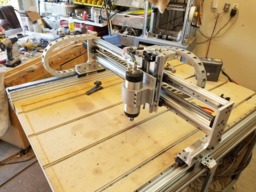
Sphinx Upgraded plates / ballscrews and linear rail

Discussion in 'CNC Mills/Routers' started by Troy Proffitt, Dec 11, 2018.

Tags:
  1. Troy Proffitt

    Troy Proffitt Journeyman
    Builder

    Joined:
    Oct 11, 2016
    Messages:
    126
    Likes Received:
    101
    Yep, I've done it as well, they're never the same after you rebuild them
     
  2. Gilsegev

    Gilsegev Well-Known
    Builder

    Joined:
    Feb 28, 2018
    Messages:
    48
    Likes Received:
    27
    Here's another aluminum plate I made. I ran the 2D adaptive clearing at full depth of cut (10mm) and contoured around the part relatively quickly.
    Not including the tool change in the middle, I was able to get this part cut in 24 minutes.

     
  3. Clark222

    Clark222 New
    Builder

    Joined:
    Feb 17, 2016
    Messages:
    24
    Likes Received:
    4
    Is there any chance you would share your Fusion 360 file. I’m having a hard time getting the holes from the drawings to line up. I was just getting ready to try and start recreating them.
     
  4. Gilsegev

    Gilsegev Well-Known
    Builder

    Joined:
    Feb 28, 2018
    Messages:
    48
    Likes Received:
    27
    I'm assuming you're asking for my model since Troy's wasn't drawn in fusion. Mine is slightly different in terms of motor mounting plates and alignment with the gantry carrying arms.
    I've uploaded my file to google drive but this comes with no guarantee. I'm recutting all these plates now so if there are any bugs in the design that I haven't caught, you'll get them too.

    Anyway, here it is:
    Sphinx CNC Upgrade - Fusion Model - Google Drive
     

    Attached Files:

    Giarc likes this.
  5. Mark Carew

    Mark Carew OpenBuilds Team
    Staff Member Moderator Builder Resident Builder

    Joined:
    Jun 28, 2013
    Messages:
    2,758
    Likes Received:
    2,440
    @Gilsegev are you feeling any deflection on X axis with the double rails when moving front to back? Trying to get an idea on how stiff the 2 40x40s are in that direction.
    Thanks
     
  6. Troy Proffitt

    Troy Proffitt Journeyman
    Builder

    Joined:
    Oct 11, 2016
    Messages:
    126
    Likes Received:
    101
    I'm using a 14lb watercooled spindle and there is no noticeable deflection
     
    Mark Carew likes this.
  7. Gilsegev

    Gilsegev Well-Known
    Builder

    Joined:
    Feb 28, 2018
    Messages:
    48
    Likes Received:
    27
    I haven't done any advanced accuracy measurements on my machine yet. I had to make several manual adjustments to the holes of the motor mount plates so I know my motors and ball screws aren't sitting straight now. This is why I redrew the design in fusion and now I am recutting all the plates. I want to get it all to align perfectly.
     
    Steveathome and Mark Carew like this.
  8. Mark Carew

    Mark Carew OpenBuilds Team
    Staff Member Moderator Builder Resident Builder

    Joined:
    Jun 28, 2013
    Messages:
    2,758
    Likes Received:
    2,440
    Thank you guys for the update and information :thumbsup:
     
    Gilsegev likes this.
  9. Clark222

    Clark222 New
    Builder

    Joined:
    Feb 17, 2016
    Messages:
    24
    Likes Received:
    4
    Thank you very much for posting the file. I’m new to fusion so the extra help is appreciated. Troys design (and your redraw) are my favorites!
     
  10. Gilsegev

    Gilsegev Well-Known
    Builder

    Joined:
    Feb 28, 2018
    Messages:
    48
    Likes Received:
    27
    Sure thing. Let me know if you need any help with the fusion file. It took a lot of fiddling to create so could be challenging to use.
     
  11. Troy Proffitt

    Troy Proffitt Journeyman
    Builder

    Joined:
    Oct 11, 2016
    Messages:
    126
    Likes Received:
    101
    Its been a great machine. I've been using it in this configuration for over a year without problems. Right now, I'm cutting about 200 Lancaster balustrades for my parents home
     
  12. Gilsegev

    Gilsegev Well-Known
    Builder

    Joined:
    Feb 28, 2018
    Messages:
    48
    Likes Received:
    27
    Agree! I've been pushing mine milling aluminum and so far she's been rock solid. Got her up to 15% EM diameter optimal load in 2D adaptive and no problem.
     
  13. xfireshotz

    Builder

    Joined:
    Oct 10, 2016
    Messages:
    3
    Likes Received:
    0
    @Gilsegev What spacing did you use in the Z axis design to ensure the BK10 support didn't interfere with the Z axis plate? I took a look at your fusion file and unfortunately the Z axis design looks different than your videos. The BK10 support has a height of 39mm and using a SFU1204 ball screw with the available ball screw nut and HGR15 rails, the spacing is 37mm, leading to a 2mm interference. Take a look at the attached picture. It seems like there should be an easily solution and I'd rather not pocket out the Z axis plate.
     

    Attached Files:

  14. Gilsegev

    Gilsegev Well-Known
    Builder

    Joined:
    Feb 28, 2018
    Messages:
    48
    Likes Received:
    27
    You're right. The z axis design on my is missing two standoffs I had to create to get the rails and blocks to line up nicely with the end supports. I *think* the standoffs were 17mm high and made of hard acrylic I had at the time. I can measure them again tomorrow.
     

    Attached Files:

    • 1.jpg
      1.jpg
      File size:
      156.1 KB
      Views:
      75
  15. xfireshotz

    Builder

    Joined:
    Oct 10, 2016
    Messages:
    3
    Likes Received:
    0
    Thanks for the image. I actually have some standoffs in my design too, I just put them in between the rail block and Z axis plate. Are you using the standard china SFU1204 nut block that is 30mm tall? Using that, I would need another standoff between the nut block and the Z axis plate to raise it higher.
     

    Attached Files:

  16. Gilsegev

    Gilsegev Well-Known
    Builder

    Joined:
    Feb 28, 2018
    Messages:
    48
    Likes Received:
    27
    Yes, I'm using BK12/BF12 end supports.
    I also recommend considering a stiffer arrangement for the z axis motor. It's currently mounted using 3 screws into the top profile of the z plate but this creates a flex point. I don't have a direction how to resolve this yet though.
     
  17. Gilsegev

    Gilsegev Well-Known
    Builder

    Joined:
    Feb 28, 2018
    Messages:
    48
    Likes Received:
    27
    By the way, I went in a rechecked my design and looks like I did have the standoffs modeled but didn't have the correct hight for them to work with BK12/BF12 end supports. I'll fix it now.

    upload_2020-5-16_22-12-18.png
     
  18. xfireshotz

    Builder

    Joined:
    Oct 10, 2016
    Messages:
    3
    Likes Received:
    0
    I think I figured out my issue. I was assuming you were using a 12mm ball screw on the Z axis but when you mentioned BK12 then you are using 16mm ball screws. The spacing on the 16mm ball screws makes it way easier to put this together so I'm going to switch to those. It will only extend my Z axis assembly cantilever 6mm so that shouldn't cause too much additional flex.

    For your motor mount, a simple solution could be to add some of those cast corner brackets if you can fit them in there. Or bolt it to those acrylic standoffs..
     
  19. Gilsegev

    Gilsegev Well-Known
    Builder

    Joined:
    Feb 28, 2018
    Messages:
    48
    Likes Received:
    27
    Yup. I'm using 1605 - sorry for not being clear about this..
    I am modelling the end supports and 1605 ball screw now. My math say that the standoff will be 17mm. I'll have the model confirm it soon enough:

    - Ball screw is 25mm off the z plate + 20mm from the screw to the edge of the nut housing/spindle plate --> height of spindle plate from z plate = 45mm
    - HIWIN block + rail height= 28mm
    ----------------------------------------------
    Standoff = 45-28 = 17mm

    I was thinking about an angle or a a bracket of some kind but need to see how to make it work still.
     
  20. Gilsegev

    Gilsegev Well-Known
    Builder

    Joined:
    Feb 28, 2018
    Messages:
    48
    Likes Received:
    27
    I confirm 17mm for the spindle plate standoffs for SFU1605 ball screw.

    I have uploaded a new version to my google drive in case you want the updated model.

    upload_2020-5-16_23-22-53.png

    upload_2020-5-16_23-23-57.png
     
  21. Gilsegev

    Gilsegev Well-Known
    Builder

    Joined:
    Feb 28, 2018
    Messages:
    48
    Likes Received:
    27
    Here is a video showing my CNC rebuild and upgrade to linear rails and ball screws based on my fusion model and design. This and some of my delightful commentary :)

    She turned out great! Very happy so far.

     
    graveur and Giarc like this.
  22. Troy Proffitt

    Troy Proffitt Journeyman
    Builder

    Joined:
    Oct 11, 2016
    Messages:
    126
    Likes Received:
    101
    Watched the whole thing. Great editing:) You should post that up on Reddit hobby cnc as well!
     
  23. Gilsegev

    Gilsegev Well-Known
    Builder

    Joined:
    Feb 28, 2018
    Messages:
    48
    Likes Received:
    27
    Thanks!! Will do
     
  24. Clark222

    Clark222 New
    Builder

    Joined:
    Feb 17, 2016
    Messages:
    24
    Likes Received:
    4
    Great video!
     
  25. Gilsegev

    Gilsegev Well-Known
    Builder

    Joined:
    Feb 28, 2018
    Messages:
    48
    Likes Received:
    27
    Thanks! Video editing isn't my thing so it took me forever to get it done.
     
  26. Clark222

    Clark222 New
    Builder

    Joined:
    Feb 17, 2016
    Messages:
    24
    Likes Received:
    4
    Did your holes end up accurate on the fusion 360 file?
     
  27. Gilsegev

    Gilsegev Well-Known
    Builder

    Joined:
    Feb 28, 2018
    Messages:
    48
    Likes Received:
    27
    Yes 100% perfect. I didn't have to drill or enlarge a single hole in the plates!
     
  28. Asparagus Marmalade

    Builder

    Joined:
    Nov 18, 2023
    Messages:
    1
    Likes Received:
    0
    Great Vid. Quick question, I couldn't see any lock nuts on the BK12 mounts for X or Y axes......Can you confirm whether you used them?
     
  29. Binoy

    Binoy New
    Builder

    Joined:
    Sep 3, 2020
    Messages:
    7
    Likes Received:
    0
    Hello ,
    Left side plate file is not open. I am looking for long time for upgrade my lead 1010.Finally I got it.
     
  30. Binoy

    Binoy New
    Builder

    Joined:
    Sep 3, 2020
    Messages:
    7
    Likes Received:
    0
    Whats the length of ball screws and linear rails for x axis we need to upgrade. Please reply. My plan is 1000 mm linear rail and ball scew. Do i need rails smaller than ball screw.
     

Share This Page

  1. This site uses cookies to help personalise content, tailor your experience and to keep you logged in if you register.
    By continuing to use this site, you are consenting to our use of cookies.
    Dismiss Notice