Welcome to Our Community

Some features disabled for guests. Register Today.

LINEAR RAIL SPHINX 55 (Blue OX plates)

Discussion in 'CNC Mills/Routers' started by that-jim, May 2, 2020.

  1. that-jim

    that-jim Journeyman
    Builder

    Joined:
    Apr 19, 2020
    Messages:
    143
    Likes Received:
    154
  2. Corey Corbin

    Corey Corbin Well-Known
    Builder

    Joined:
    Feb 27, 2016
    Messages:
    135
    Likes Received:
    62
    Hi, I was wondering how is the cnc machine build going? I was curious if you have got it going to notice if the MGN12 alignment block for the rails works good or you do think you still have to use dial indicator?
     
  3. that-jim

    that-jim Journeyman
    Builder

    Joined:
    Apr 19, 2020
    Messages:
    143
    Likes Received:
    154
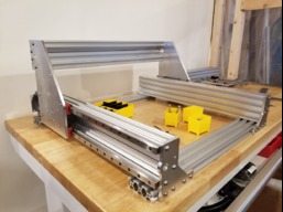
    Corey, well... it is going kind of slow. I did get all of the hardware for attaching the rails and they are now on. At first I tried a 3d printed guide for rail alignment but was not satisfied with the result. So I made an aluminum block that I bolted to the extrusion, this block has an adjustable screw for setting the rails. like this, there are t nuts holding it on so you can push the rail against it then snug down the rail

    20200505_184825.jpg


    This worked very well, I did check the rails with an indicator afterword but they seemed perfect. I think this measuring step is not really necessary but it was reassuring to confirm that my alignment jig worked.


    20200504_213033.jpg

    Once I set and tightened the top rail I loosely assembled the bottom rail, side plate and rail blocks. Then I slid the side plate back and forth and snugged up the bottom rail and blocks. I figured that this would align the bottom rail to the top rail and as far as I can tell it did the trick.
     
    #3 that-jim, May 14, 2020
    Last edited: May 14, 2020
    REdington likes this.
  4. Giarc

    Giarc OpenBuilds Team
    Staff Member Moderator Builder Resident Builder

    Joined:
    Jan 24, 2015
    Messages:
    3,017
    Likes Received:
    1,682
    That aluminum block and screw are brilliant. I was just trying to come up with something to do the same thing, but you did it for me. Awesome! thanks.
     
    Peter Van Der Walt likes this.
  5. Corey Corbin

    Corey Corbin Well-Known
    Builder

    Joined:
    Feb 27, 2016
    Messages:
    135
    Likes Received:
    62
    Good idea! Thanks for sharing. I was a little on the fence about 3d printing the guide but I was gonna try it. Only reason why is I know my 3d printer. And I figured I print it up and something would be off. But I like your idea better. Glad I asked, I am still sourcing parts so haven't got my rails yet. I have had to redo
    Z axis plate so machine is apart right now. But as soon as I can cut aluminum reliably I plane to make some plates and upgrade to rails system or just start another bigger machine. Thanks!
     
  6. Corey Corbin

    Corey Corbin Well-Known
    Builder

    Joined:
    Feb 27, 2016
    Messages:
    135
    Likes Received:
    62
    Nice update! Machine looking good. I also like the thrust bearing and washer Idea! Did you push the motor drive coupler just snug?
     
  7. that-jim

    that-jim Journeyman
    Builder

    Joined:
    Apr 19, 2020
    Messages:
    143
    Likes Received:
    154
    Thanks Corey. Yes the motor coupling is 'just' pushed against the thrust washer. I have cut a few projects with the machine so far and everything seems to be working well.
     
  8. ICT Avatar

    Builder

    Joined:
    Apr 25, 2018
    Messages:
    6
    Likes Received:
    2
  9. that-jim

    that-jim Journeyman
    Builder

    Joined:
    Apr 19, 2020
    Messages:
    143
    Likes Received:
    154
    Those should work, they look exactly like the ones I used.
     
  10. Hector Beltran

    Hector Beltran Well-Known
    Builder

    Joined:
    Oct 14, 2017
    Messages:
    61
    Likes Received:
    26
    Where can I get linear rails for this project? I am converting a workbee1010 to linear rails. Chris is sourcing the plates
    Deluxe 2" taller Linear Rail Sphinx CNC Plate Set (seen at Openbuilds) | eBay
    , so I’ll need the rest of the hardware including screws, nuts and everything else. I’ve never bought linear rails from eBay or anywhere else for that matter. Don’t want to get stuck with junk specially since installing this upgrade takes a few hours to do. Any suggestions?
     
  11. Giarc

    Giarc OpenBuilds Team
    Staff Member Moderator Builder Resident Builder

    Joined:
    Jan 24, 2015
    Messages:
    3,017
    Likes Received:
    1,682
    Myself and others here have purchased these. I bought three sets, but could probably got away with 2. I use a top and bottom for each side of the y axis. I plan to cut another set to 1000 mm for the x with the leftover pieces for the 500 mm z axis. I am doing a homebrew high z mod to mine using the Openbuilds high z kit. I did have to order 4 extra bearings for the z.
    https://www.amazon.com/OrangeA-15-1...rds=linear+rails+1500mm&qid=1603741785&sr=8-4
     
  12. that-jim

    that-jim Journeyman
    Builder

    Joined:
    Apr 19, 2020
    Messages:
    143
    Likes Received:
    154

    I got the rails I used for this build from the following links
    https://www.amazon.com/gp/product/B07Z5NKF42/ref=ppx_yo_dt_b_search_asin_title?ie=UTF8&psc=1
    Machifit MGN12 100-1000mm Linear Rail Guide with MGN12H Linear Sliding Guide Block CNC Parts Machine Tools & Accessories from Tools on banggood.com

    I did have to spend some time cleaning the factory oil from the bearings and rails and then re-lube them, but they seem to work well.

    The plate set I got from Chris had spacers that work with the 12mm MGN12 rails, so you will have to verify what height of rail and bearing works with your set up.
     
  13. Hector Beltran

    Hector Beltran Well-Known
    Builder

    Joined:
    Oct 14, 2017
    Messages:
    61
    Likes Received:
    26
    Thank you guys. Any do’s/don’ts when cutting the linear rails to size? Thinking of using a jigsaw with a blade for metal. I don’t own a grinder but I could borrow one.
     
  14. Giarc

    Giarc OpenBuilds Team
    Staff Member Moderator Builder Resident Builder

    Joined:
    Jan 24, 2015
    Messages:
    3,017
    Likes Received:
    1,682
    I was just going to use a sawzall with a metal blade and if that doesn't work, an angle grinder.
     
  15. Hector Beltran

    Hector Beltran Well-Known
    Builder

    Joined:
    Oct 14, 2017
    Messages:
    61
    Likes Received:
    26
    Hi again, I wanted to bounce a couple of ideas by you guys that have gone thru a similar upgrade. Seems like with Covid, linear rails are hard to come by. I checked the Amazon link and they were out and the banggood are partially out as well.
    I came across this vendor in Texas
    ZYLtech Engineering LLC that has the rails. Adding rails and plates, I am close to $720. I also came across https://www.cnc3d.com.au/ which sells the entire kit using linear rails (a bit bigger blocks I think) with all the bolts, shims and others misc for about $920 delivered. I was wondering if $720 plus all additional hardware is the best route. Anyone has experience with cnc3d?
     
  16. marspeed

    marspeed New
    Builder

    Joined:
    Nov 4, 2020
    Messages:
    1
    Likes Received:
    0
    I cut my rails with a grinder with metal cut off disc
     
  17. King_Splat

    Builder

    Joined:
    Apr 24, 2018
    Messages:
    3
    Likes Received:
    0
    Hi Jim, Great work! Can you please post your Spindle Mount Bracket? That looks like a good upgrade I would like to make for my machine. Thank you
     
  18. Hector Beltran

    Hector Beltran Well-Known
    Builder

    Joined:
    Oct 14, 2017
    Messages:
    61
    Likes Received:
    26
    Hi Guys,

    I am almost finished with the update to linear rails on my Workbee. I ended up buying the rails from ZYLtech. They were expensive but they are a Texas based company. The blocks are OK but I wish they were smoother on the rails. We’ll see how they perform. Since I took everything apart, I decided to redo certain things differently this time. For the spoilboard, I went with all aluminum extrusions and will add MDF slats instead of a large board. I’ll use the extrusions to anchor bolts on the v-slots, so I can hold parts. It should be more rigid and easier to replace slats than an entire spoilboard. I need to 3D print new plastic brackets to hold the cable chains as the z and y gantry plates are very different. All things considered, it’s been a long process but mainly due to having little time to work on it. Looking forward to CNC’ing again. Will post some pictures when it’s finished to help out anyone else attempting to do it.
     
  19. King_Splat

    Builder

    Joined:
    Apr 24, 2018
    Messages:
    3
    Likes Received:
    0
  20. Hector Beltran

    Hector Beltran Well-Known
    Builder

    Joined:
    Oct 14, 2017
    Messages:
    61
    Likes Received:
    26
    Yes. I got the plates from Chris. You’ll need to order two anti-backlash for the Y axes from Openbuilds. For the screws and t-nuts I went to Amazon. Also, pickup a bag of 100 3/32 ball bearings cause you are bound to loose some. I did loose one and had to wait a couple of days for Amazon. Let me know if you need any help.
     
  21. that-jim

    that-jim Journeyman
    Builder

    Joined:
    Apr 19, 2020
    Messages:
    143
    Likes Received:
    154

    King, Here are links to the fusion 360 files for that bracket

    bracket
    CAM file for bracket

    Let me know if you want it in another format, hopefully it works well for you.
     
  22. King_Splat

    Builder

    Joined:
    Apr 24, 2018
    Messages:
    3
    Likes Received:
    0
    Thank you! Can't want to make one of my own!
     
  23. lpn9

    lpn9 New
    Builder

    Joined:
    Mar 16, 2014
    Messages:
    2
    Likes Received:
    0
    Hi Jim,
    After years of looking, going to spend some saved cash and build one. I was wanting a design like yours (thinking that the rails offer better accuracy over the wheels), but was hoping to expand like the C-beam Sphinx (shooting for 1000 Y, 750 X). I like the open work path giving the option to stitch work paths for longer products. I was wondering with your design, and if I used the cut size from C-beam Sphinx 1000 x 750, would I at least get 24" cut distance in the X? Would primarily be used on wood products (MDF - hardwoods), plastic/acrylic, (and maybe aluminum, or would the size exclude this?).

    Thanks
    Dom
     
  24. that-jim

    that-jim Journeyman
    Builder

    Joined:
    Apr 19, 2020
    Messages:
    143
    Likes Received:
    154
    I have a footprint of roughly 500x500 and a cut area of 325 x 335, at 750 x 1000 you should be able to have a cut area of 575 x 835 or 22.6" x 32.8". I think you would have to custom cut the x (beam and screw) to get 750 so you could just cut it to around 800 and get your 24" X.

    It should work well for all these materials.
     
    #24 that-jim, Apr 13, 2021
    Last edited: Apr 13, 2021
  25. lpn9

    lpn9 New
    Builder

    Joined:
    Mar 16, 2014
    Messages:
    2
    Likes Received:
    0
    Thanks Jim,
    Much appreciation to you and all the other builders on this site for sharing.
    Dom
     
  26. imark007

    imark007 New
    Builder

    Joined:
    Mar 17, 2020
    Messages:
    2
    Likes Received:
    0
    Nice build! I was wondering what the maximum height of part is that can fit in the machine. I want to make cut-outs in the top and bottom of plastic enclosures that measure 150 mm (5.9 inches) from top to bottom. Will this part clear a mill in a router?
     
  27. that-jim

    that-jim Journeyman
    Builder

    Joined:
    Apr 19, 2020
    Messages:
    143
    Likes Received:
    154

    I have 120mm between the bottom of the z-axis and the top of spoil-board, so your enclosure would not fit the way mine is configured. If you removed the spoil-board and reconfigure the frame a bit you could likely find a way to machine your enclosures. If you put some thought into it you could probably configure the bed of a machine like this (link).
     
    Peter Van Der Walt likes this.
  28. imark007

    imark007 New
    Builder

    Joined:
    Mar 17, 2020
    Messages:
    2
    Likes Received:
    0
    Thanks for the information. I was studying the Stepcraft machine setup and then found this link that is probably the most versatile for me (although I probably won't try to tackle the 5th axis).
     
  29. that-jim

    that-jim Journeyman
    Builder

    Joined:
    Apr 19, 2020
    Messages:
    143
    Likes Received:
    154
    Sounds like you are on to a cool solution, the beauty of the openbuilds stuff is that you can take a machine and rework it to fit your needs.
     
  30. Hector Beltran

    Hector Beltran Well-Known
    Builder

    Joined:
    Oct 14, 2017
    Messages:
    61
    Likes Received:
    26
    Here is my updated workbee. It now has linear rails on all 3 axes, aluminum extrusions below the spoil board, and a better spoil board design. It should be easier to hold down my work pieces and replace damaged boards on the spoil board. It took me a while as I had to disassemble just about everything. I am happy with the results so far. I need calibrate and run some jobs; the first one will be to make an aluminum bracket for the cable track on the X gantry. I also need to cover the top of the enclosure as some saw dust still makes it way out. I will probably use plexiglass to let some light in.
     

    Attached Files:

    REdington, Rhett E and Giarc like this.

Share This Page

  1. This site uses cookies to help personalise content, tailor your experience and to keep you logged in if you register.
    By continuing to use this site, you are consenting to our use of cookies.
    Dismiss Notice