Welcome to Our Community

Some features disabled for guests. Register Today.

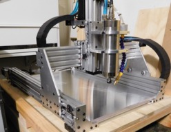
7050 Sphinx

Discussion in 'CNC Mills/Routers' started by Michael.M, Jul 15, 2017.

  1. Michael.M

    Michael.M Veteran
    Staff Member Builder Resident Builder

    Joined:
    Jan 21, 2017
    Messages:
    432
    Likes Received:
    266
    Hey let me look around for it. That was quite a while ago but if I don't still have it, I know how I made it. Give me a bit.
     
  2. Michael.M

    Michael.M Veteran
    Staff Member Builder Resident Builder

    Joined:
    Jan 21, 2017
    Messages:
    432
    Likes Received:
    266
    Do you have SketchUp? The reason I ask is I remember having to fiddle around with the right printer settings to get an actual scale picture of the sketchup plate model
     
  3. Michael.M

    Michael.M Veteran
    Staff Member Builder Resident Builder

    Joined:
    Jan 21, 2017
    Messages:
    432
    Likes Received:
    266
    Here's the plate with the two extra holes marked with a "+" in the middle. I am now trying to remember how I printed an actual size picture of the front face
     

    Attached Files:

  4. Giarc

    Giarc OpenBuilds Team
    Staff Member Moderator Builder Resident Builder

    Joined:
    Jan 24, 2015
    Messages:
    3,018
    Likes Received:
    1,688
    For making 1:1 templates from Sketchup, You can download this sketchup plugin at this link, then install as you would any other sketchup plugin.
    Post script plot

    If your computer can not view Postscript files, install Ghostview ( it needs Ghostscript to work ) It works really well for me.
    Obtaining GSview 5.0 This is how I made all my hand cut and drilled plates. I also put an x in the middle to make drilling more accurate.
     
    Kyo and Michael.M like this.
  5. Michael.M

    Michael.M Veteran
    Staff Member Builder Resident Builder

    Joined:
    Jan 21, 2017
    Messages:
    432
    Likes Received:
    266
    Awesome! That's a great tip. Thank you.
     
  6. mortorojo

    mortorojo New
    Builder

    Joined:
    May 4, 2016
    Messages:
    6
    Likes Received:
    1
    Thanks, this worked great once the model face needed was rotated to the camera front.
     
  7. mortorojo

    mortorojo New
    Builder

    Joined:
    May 4, 2016
    Messages:
    6
    Likes Received:
    1
    Im trying to figure out how you mounted your drag chain on the x-axis without the gantry hitting it on move.
     
  8. Michael.M

    Michael.M Veteran
    Staff Member Builder Resident Builder

    Joined:
    Jan 21, 2017
    Messages:
    432
    Likes Received:
    266
    You're talking about the longer chain that runs down the y axis?
     
  9. mortorojo

    mortorojo New
    Builder

    Joined:
    May 4, 2016
    Messages:
    6
    Likes Received:
    1
    The one on the back of your x-axis. I see it is mounted to the z cbeam, but i don't see how you mounted it on the other end by the x-stepper.
     
    #339 mortorojo, Apr 29, 2018
    Last edited: Apr 29, 2018
  10. Sprags

    Sprags Well-Known
    Builder

    Joined:
    Nov 23, 2017
    Messages:
    154
    Likes Received:
    13
    Let me get your thoughts on building a 'table' for my machine using 20 X 40 extruded aluminum rails for the frame of the table? I'm even considering not having a table top either ...just attaching the machine to the frame itself. I thought about building a wooden bench but I don't have woodworking tools setup to do that. I also considered buying an ikea table to use. IKEA happens to have a nice table made completely out of wood, including the table top, for $200. I bought and used one in my condo in Cincinnati. In my current home I have a complete dining set and a nicer kitchen set so I'm using for a hobby table for my electronics. Another one would be nice for the CNC but I'm thinking an extruding aluminum rail table would be nice so I can easily rebuild the machine since it will be open on the bottom. Plus it would be ideal for attaching the controller box .

    Incidentally I bought my controller box from Automation Technologies in Streamwood, Illinois. They are kind of dysfunctional but they are nice and willing to help as best as they can.
     
  11. Michael.M

    Michael.M Veteran
    Staff Member Builder Resident Builder

    Joined:
    Jan 21, 2017
    Messages:
    432
    Likes Received:
    266
    Hey sorry i didn't get back to you sooner. The chain runs parallel to the x axis on a small L shaped aluminum profile. The end of the chain is bolted to a small piece of flat bar that's then bolted to the L profile. At the time, this was all just a trial and error but it's worked well 20180505_102716.jpg
     
  12. Michael.M

    Michael.M Veteran
    Staff Member Builder Resident Builder

    Joined:
    Jan 21, 2017
    Messages:
    432
    Likes Received:
    266
    The L profile is bolted to the Y plates using the extra holes from the original motor mounting points. 20180505_103303.jpg
     
  13. Michael.M

    Michael.M Veteran
    Staff Member Builder Resident Builder

    Joined:
    Jan 21, 2017
    Messages:
    432
    Likes Received:
    266
    I am using something similar to this. It works for now. It's also heavy. Im not sure aluminum extrusions would be sturdy enough to be honest.
     
  14. HuguesP

    HuguesP Well-Known
    Builder

    Joined:
    Jan 14, 2018
    Messages:
    30
    Likes Received:
    44
    hey nice build, looks very professional all aluminum!
     
    Michael.M likes this.
  15. Michael.M

    Michael.M Veteran
    Staff Member Builder Resident Builder

    Joined:
    Jan 21, 2017
    Messages:
    432
    Likes Received:
    266
    Hey thank you! Please let me know if you need any more details. The OpenBuilds team have been amazingly helpful people to work with.
     
  16. Michael.M

    Michael.M Veteran
    Staff Member Builder Resident Builder

    Joined:
    Jan 21, 2017
    Messages:
    432
    Likes Received:
    266
    Hey it looks like your machine is coming along nicely. I am currently working on upgraded plates to utilize ballscrews and linear rails.
     
  17. Michael.M

    Michael.M Veteran
    Staff Member Builder Resident Builder

    Joined:
    Jan 21, 2017
    Messages:
    432
    Likes Received:
    266
    Currently testing my new DIY fogless coolant setup. 1/2" 6061 / 4.5mm 2FL carbide. Working on dialing in Feeds & Speeds. DSCN1782.JPG DSCN1780.JPG DSCN1781.JPG
     
    Kyo likes this.
  18. HuguesP

    HuguesP Well-Known
    Builder

    Joined:
    Jan 14, 2018
    Messages:
    30
    Likes Received:
    44
    i would warn you to go the aliexpress way, the rails and carriers i got are not of the best quality! Having a CNC to build the next CNC, is probably a must have! iam not finish with my first build and i am already thinking about things a would do different!
     
  19. Michael.M

    Michael.M Veteran
    Staff Member Builder Resident Builder

    Joined:
    Jan 21, 2017
    Messages:
    432
    Likes Received:
    266
    I bought used THK linear rails and carriages before I built the Sphinx as I was looking to build a machine of my own design. I'm just now getting around to using them lol.
     
    HuguesP likes this.
  20. Michael.M

    Michael.M Veteran
    Staff Member Builder Resident Builder

    Joined:
    Jan 21, 2017
    Messages:
    432
    Likes Received:
    266
    So the first test went ok with the new water based coolant system. Side finish is still not perfect but better than before. I can see I am still re-cutting my chips and leaving small marks on the side. I believe I need a nozzle on both sides of the spindle. I'm still not able to take more than .3 - .4mm DOC without some chatter but a lot of this is dialing in feeds and speeds. Before this cooling system, I would have absolutely terrible side finish about 1/3 from the bottom but again, chip evacuation is critical for a nice clean surface finish. This piece was done with no final finishing pass, just standard contour operation. DSCN1787.JPG DSCN1784.JPG DSCN1785.JPG
     
    #350 Michael.M, May 26, 2018
    Last edited: May 26, 2018
    Kyo likes this.
  21. Michael.M

    Michael.M Veteran
    Staff Member Builder Resident Builder

    Joined:
    Jan 21, 2017
    Messages:
    432
    Likes Received:
    266
    Actually I can hear the endmill grinding the chips left in the cut from the previous pass. The machine would probably be 1/2 as loud if I could clear all of them.
     
  22. James_Hopkins

    Builder

    Joined:
    Jul 16, 2015
    Messages:
    28
    Likes Received:
    6
    Great build. Im going to start cutting the plates on my C-beam machine.
    I use fusion 360 for my cad and cam. I can’t figure out how to get the plates in fusion so I can cut them.

    Do you have a fusion 360 drawing of the Sphinx so I can pull the plates out machine them?
     
  23. Michael.M

    Michael.M Veteran
    Staff Member Builder Resident Builder

    Joined:
    Jan 21, 2017
    Messages:
    432
    Likes Received:
    266
    Kyo has SketchUp and Fusion Sphinx models included in his build guide. They are the shorter gantry plates though. I don't think I have a Fusion model of the gantry plates. I did a mock up in Sketchup. I can get you the dimensions if you want to alter the shorter plates.
     
  24. CNCMD

    CNCMD Journeyman
    Builder

    Joined:
    Jul 29, 2017
    Messages:
    148
    Likes Received:
    115
    Hey Michael - I concur with you on needing dual nozzles for blowing chips. I haven't incorporated a second nozzle yet, but I completely see that it would be very helpful in chip evacuation.

    Side finish on that part looks great considering no finishing pass.
     
    Michael.M likes this.
  25. HuguesP

    HuguesP Well-Known
    Builder

    Joined:
    Jan 14, 2018
    Messages:
    30
    Likes Received:
    44
    i was also wondering if you only blow air or you happen to also mist coolant? i have seen video of dual nozzle fog buster and it seems to do the job quite well, unfortunatly the price range of the fog buster is... i was wondering if similar result can be achieved with std ebay mist/air nozzle. most of my reading lead me to think that cheap nozzle will blow more fog than droplets!
     
  26. Michael.M

    Michael.M Veteran
    Staff Member Builder Resident Builder

    Joined:
    Jan 21, 2017
    Messages:
    432
    Likes Received:
    266
    Thanks buddy. Here's some more pictures. These are the ballscrew parts I am finally getting around to. You can see in the first picture the finish is great except for a weird bump where the machine lifts up to create a work holding tab (I must have some backlash or tool deflection). That first picture you commented on was an "L" shaped piece that allowed me to perform almost perfect two sided machining. The last picture is of the side that the air doesn't reach. This is 1/2" material but when I run 1/4", the air can reach a lot more. DSCN1826.JPG DSCN1829.JPG DSCN1824.JPG DSCN1828.JPG
     
  27. Michael.M

    Michael.M Veteran
    Staff Member Builder Resident Builder

    Joined:
    Jan 21, 2017
    Messages:
    432
    Likes Received:
    266
    Originally I only used my mist nozzle with air and just didn't hook up the coolant but recently I built the first version of a coolant system that uses water soluble coolant. It's still not perfect. I'm trying to make a fogless system because the cheaper mist type nozzles will fill the room with a coolant fog which isn't healthy.
     
  28. CNCMD

    CNCMD Journeyman
    Builder

    Joined:
    Jul 29, 2017
    Messages:
    148
    Likes Received:
    115
    Those marks are common with tabs for some reason. Parts look very good, I'll have to send you some pics of things I've been working on.
     
  29. John Aristi

    Builder

    Joined:
    Jun 4, 2018
    Messages:
    1
    Likes Received:
    0
    Hi,
    I want to build one of those beauties but where do I start? is this project, for example shares plans and files and other things or just build my own and and see what happen. I am sorry a bit lost in this website.

    regards

    john
     
  30. NeeqOne

    NeeqOne Well-Known
    Builder

    Joined:
    Mar 3, 2018
    Messages:
    46
    Likes Received:
    27
    Refer to the original build by Kyo here: https://openbuilds.com/builds/c-beam-sphinx.3605/. All the information you will need to get you started are contained in the build log and discussion thread.
     
    Michael.M and GrayUK like this.

Share This Page

  1. This site uses cookies to help personalise content, tailor your experience and to keep you logged in if you register.
    By continuing to use this site, you are consenting to our use of cookies.
    Dismiss Notice