Welcome to Our Community

Some features disabled for guests. Register Today.

7050 Sphinx

Discussion in 'CNC Mills/Routers' started by Michael.M, Jul 15, 2017.

  1. Sprags

    Sprags Well-Known
    Builder

    Joined:
    Nov 23, 2017
    Messages:
    154
    Likes Received:
    13
    That is what I need to know. So I should plan on buying longer pieces that I can cut to the exact length needed.
    Thank you.
     
  2. Michael.M

    Michael.M Veteran
    Staff Member Builder Resident Builder

    Joined:
    Jan 21, 2017
    Messages:
    432
    Likes Received:
    265
    Yeah that's what I did. I used a miter saw with a blade designed for non ferous metals but I've cut 1/2" plate with a regular carbide tipped blade in my skill saw. Cuts easier than wood! Lol
     
  3. Sprags

    Sprags Well-Known
    Builder

    Joined:
    Nov 23, 2017
    Messages:
    154
    Likes Received:
    13
    I'm planning on getting that cut guide I saw a link for somewhere on this web site. I hope I can find it again. it looks like a well build tool to use with a hack saw to get very straight and square cuts?
     
  4. Michael.M

    Michael.M Veteran
    Staff Member Builder Resident Builder

    Joined:
    Jan 21, 2017
    Messages:
    432
    Likes Received:
    265
    I saw that also. Should work just fine combined with the right hacksaw blade. Get a large file to clean up the ends.
     
  5. Sprags

    Sprags Well-Known
    Builder

    Joined:
    Nov 23, 2017
    Messages:
    154
    Likes Received:
    13
    I just placed the order...
    When I get home I will double check how long and how many rails I need and then I can place the order.
     
    #215 Sprags, Jan 9, 2018
    Last edited: Jan 9, 2018
  6. SCYBUCK

    SCYBUCK New
    Builder

    Joined:
    Sep 11, 2017
    Messages:
    36
    Likes Received:
    13
    Michael.M likes this.
  7. SCYBUCK

    SCYBUCK New
    Builder

    Joined:
    Sep 11, 2017
    Messages:
    36
    Likes Received:
    13
    Good looking build, Michael! Looks very similar to mine. However, I must take exception to one thing that you said! You noted that the build is complete. I suspect that these things are like nuclear plants. They are really never complete!
     
    Michael.M likes this.
  8. Michael.M

    Michael.M Veteran
    Staff Member Builder Resident Builder

    Joined:
    Jan 21, 2017
    Messages:
    432
    Likes Received:
    265
    You're completely right but at some point, you have to consider its first stage is complete. Plus, I want the discount for my next openbuilds purchase lol!
     
  9. Sprags

    Sprags Well-Known
    Builder

    Joined:
    Nov 23, 2017
    Messages:
    154
    Likes Received:
    13
    How about building a linear actuator that converts linear motion into rotary motion and setting it up on the dining room table do you can pass the ketchup using a stepper motor controlled by a Raspberry Pi?
     
    Michael.M likes this.
  10. Sprags

    Sprags Well-Known
    Builder

    Joined:
    Nov 23, 2017
    Messages:
    154
    Likes Received:
    13
    I got my order from Open Build and started by unpacking the loooong box. The one with the extruded aluminum rails and i suddenly realized i did not order enough of the 20 x 60 v-slot rails to build the frame the rest of the machine is going to sit on. I am also considering making my table out of the 20 x 60 v-slot rails out of also. That way having a table with slots i can attach my clamps to. Though to start out I should probably use a sheet of MDF until I get comfortable with all my software configurations go and i get an understanding of the motion of the machine. I'd rather not christen the table with a tool gouge right away like i did on my first CNC Haas machine 20 years ago.

    And I for some reason thought the lead screws had one end ground to a round surface with a flat on it for attaching the flexible couplings to. Do the flex couplings work with attaching them to the threaded portion of the lead screw? if not how have others prepped the lead screws for the flex couplings?
     
  11. Michael.M

    Michael.M Veteran
    Staff Member Builder Resident Builder

    Joined:
    Jan 21, 2017
    Messages:
    432
    Likes Received:
    265
    Yes the flex couplings work as is but you should grind flats where the lock collar set screw sits
     
  12. Sprags

    Sprags Well-Known
    Builder

    Joined:
    Nov 23, 2017
    Messages:
    154
    Likes Received:
    13
    Hmmm...

    If I had known I would have made my x-axis a little longer. I thought the 500 mm lead screw was already prepped on the one end. That being said I may order another c-beam and a 1000 mm lead screw i can just cut to length for the longer x-axis.

    As it turns out I got an email saying the Phoenix CNC controller is back in stock so I got that ordered too. Now all that is left is ordering the spindle/VFD.

    ...and the fun of putting it all together. :)
     
  13. Michael.M

    Michael.M Veteran
    Staff Member Builder Resident Builder

    Joined:
    Jan 21, 2017
    Messages:
    432
    Likes Received:
    265
    Right on dude! Feel free to ask me for help. Sorry about the mix-up with the leadscrew.
     
  14. Sprags

    Sprags Well-Known
    Builder

    Joined:
    Nov 23, 2017
    Messages:
    154
    Likes Received:
    13
    No problem. I got the idea in my head that it was prepped on one end from what i thought i saw in the YouTube build videos.
    what are your thoughts about using the extruded rails strapped together as a table? My idea is that since the table is stationary and will be attached to the frame on both ends and in the middle that i don't have to worry about it flexing and not being flush on the top surface.
     
  15. Michael.M

    Michael.M Veteran
    Staff Member Builder Resident Builder

    Joined:
    Jan 21, 2017
    Messages:
    432
    Likes Received:
    265
    I was going to do the same at one point. I may still add the extrusions. The biggest thing to keep in mind is making sure the structure underneath them is as flat as possible
     
  16. Sprags

    Sprags Well-Known
    Builder

    Joined:
    Nov 23, 2017
    Messages:
    154
    Likes Received:
    13
    Yep..I understand why.

    How big is the work area on your machine?

    I’m thinking I may build my machine to cover the same footprint as yours for now and once I see how things are running possibly increase the size later
     
  17. Michael.M

    Michael.M Veteran
    Staff Member Builder Resident Builder

    Joined:
    Jan 21, 2017
    Messages:
    432
    Likes Received:
    265
    Well my cast plate is 420mm x 700mm but I can't use the entire y axis because of the way it's setup. The x axis could be usable if your workpiece is up high enough.
     
  18. Sprags

    Sprags Well-Known
    Builder

    Joined:
    Nov 23, 2017
    Messages:
    154
    Likes Received:
    13
    OK...am i right in guessing the X-axis distance is limited roughly by the distance from the gantry plate edge to edge distance..or maybe a little more if the spindle clamps extend out past the edges? Roughly speaking of course.
     
  19. Michael.M

    Michael.M Veteran
    Staff Member Builder Resident Builder

    Joined:
    Jan 21, 2017
    Messages:
    432
    Likes Received:
    265
    I could fit 7 of those 60mm extrusions perfectly. If you go bigger you could use the 20*80
     
  20. Sprags

    Sprags Well-Known
    Builder

    Joined:
    Nov 23, 2017
    Messages:
    154
    Likes Received:
    13
    I’m not going much wider than what I have. I think 7 80mm wise rails would be good.
     
  21. Michael.M

    Michael.M Veteran
    Staff Member Builder Resident Builder

    Joined:
    Jan 21, 2017
    Messages:
    432
    Likes Received:
    265
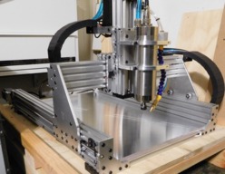
    Just figured I'd show some pictures I took tonight. I had to make adjustments so I cleaned everything for the first time in a while. DSCN1490 (2).JPG DSCN1491 (2).JPG DSCN1493 (2).JPG DSCN1495 (2).JPG
     
    Kyo and Scotty Orr like this.
  22. Sprags

    Sprags Well-Known
    Builder

    Joined:
    Nov 23, 2017
    Messages:
    154
    Likes Received:
    13
    Golly that looks nice! (I really tried to use the word 'd**n' but was censored). I just got all my stuff from OpenBuilds and Blue OX plus the mitre box...I'm still waiting on the spindle/VFD and the Phoenix CNC controller board. My plan is to use 1000 mm long C-Beams for the Y-axis and then go with a 600 mm X-axis just to give it a little more travel. Because of that I'm thinking I should call it a Kyo Sphinx 10060...but my fellow engineering co-workers say I should name it the Blake 2000.

    Question. Since this has a stationary table is this considered a Cartesian machine or an XY Table machine? I'm asking so I know how to submit my build.

    One more question. Can you post a photo of the rear view of the machine? I just want to see how you have yours set up so I can plagerize the hell out of it.
     
    #232 Sprags, Jan 20, 2018
    Last edited: Jan 20, 2018
  23. Michael.M

    Michael.M Veteran
    Staff Member Builder Resident Builder

    Joined:
    Jan 21, 2017
    Messages:
    432
    Likes Received:
    265
    I am using the OpenBuilds reduction plate on the X and Z axis. I had to modify a couple of the holes for it to work with the X but it was really no big deal. The way the machine is sitting right now, it's hard to get a good picture with enough light. I will try to take some better pics tomorrow when the sun is up but if you look at some of my older pictures on the first page, you should see the arrangement. DSCN1504.JPG DSCN1508.JPG
     
  24. Sprags

    Sprags Well-Known
    Builder

    Joined:
    Nov 23, 2017
    Messages:
    154
    Likes Received:
    13
    Just out of curiosity can you tell me the approximate dimensions of the VFD? I'm trying to get some ideas for an exclosure for the electronics.

    I bought the Blue Ox Kyo Sphinx Tall 9 plate set based on what Chris told me about that extra plate. I'm not sure if that plate solves the issue you just mentioned but I'll find out when I get there.

    Right now I'm watching a YouTube Sphinx build video. The video overall is ok...

    I also watched a video on a controller setup using the Phoenix CNC board, a Raspberry
    Pi and bCNC/GRBL setup...which is what I think I'm going to try first.

    I did not get an M5 X .8 tap and after seeing a video that uses self tapping screws I think I'm going to just use those to tap the rails. It seems that since the screws have a lead in there is less of a chance of stripping out the first thread or two. If I had a thread guide I wouldn't have a problem with using a regular tap....but I don't. I probably won't use. The self tapping screws for actual fastening since I bought lots of extra screws already.
     
    #234 Sprags, Jan 20, 2018
    Last edited: Jan 20, 2018
  25. Michael.M

    Michael.M Veteran
    Staff Member Builder Resident Builder

    Joined:
    Jan 21, 2017
    Messages:
    432
    Likes Received:
    265
    I 3d printed a tap guide that was designed for use with the vslot. Do you have or know anyone with an FDM printer?
     
  26. Sprags

    Sprags Well-Known
    Builder

    Joined:
    Nov 23, 2017
    Messages:
    154
    Likes Received:
    13
    I do not...so it was probably your tap guide I saw and liked..would you be willing to make one for me for a reasonable dollar amount?

    I noticed the blue ox plates could possibly allow two lead screw anti backlash nuts to be installed. And the video I watched talked about the center distance on the v1.0 plates are wrong. I'm wondering if the plates I have are corrected for using two per lead screw which I'm assuming allows for adjusting to have even more accuracy. Would you by chance know? Or I may need to ask Chris.
     
  27. Michael.M

    Michael.M Veteran
    Staff Member Builder Resident Builder

    Joined:
    Jan 21, 2017
    Messages:
    432
    Likes Received:
    265
    Yeah they are correct for two per axis. I could print you one if you pay for shipping.
     
  28. Sprags

    Sprags Well-Known
    Builder

    Joined:
    Nov 23, 2017
    Messages:
    154
    Likes Received:
    13
    I'll send you a PM with my contact info...thank you
     
  29. Michael.M

    Michael.M Veteran
    Staff Member Builder Resident Builder

    Joined:
    Jan 21, 2017
    Messages:
    432
    Likes Received:
    265
    Ok so I am milling a small object that requires a couple different bit changes. The first time I run the engraving op, it ends up way too deep so I decide to try the whole thing again from a clean piece of the 6061. I swap back to my .25" 2FL endmill for facing but I forgot to re-zero the z axis. So I end up making one pass 3mm deep, 50% step over!! I've never scrambled so fast to the machine lol. There was some chatter but it was plowing right through. If this was an 1/8" bit, no way it would have survived. It's also a good thing the start of the cut move was on the outside edge of the material so no plunge happened. DSCN1520.JPG DSCN1522.JPG
     
  30. Michael.M

    Michael.M Veteran
    Staff Member Builder Resident Builder

    Joined:
    Jan 21, 2017
    Messages:
    432
    Likes Received:
    265
    I have nothing but good things to say about the Kyocera Endmills. I really don't see any need to buy anything more expensive.
     

Share This Page

  1. This site uses cookies to help personalise content, tailor your experience and to keep you logged in if you register.
    By continuing to use this site, you are consenting to our use of cookies.
    Dismiss Notice