Welcome to Our Community

Some features disabled for guests. Register Today.

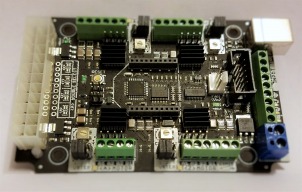
CNC xPRO Driver

Discussion in 'Other Builds' started by Spark Concepts, May 25, 2014.

  1. Justin Dewoody

    Builder

    Joined:
    May 23, 2015
    Messages:
    49
    Likes Received:
    0
    Hey guys...I have my CNC xPRO V2 up and running. All is working just fine except for the PWM spindle speed control. When I turn everything on, my spindle just goes one speed. I have no idea what RPM it's running. But I cannot stop it or change it. I have the spindle/speed controller/xpro wired up just like instructed on the pro's front build page (http://openbuilds.com/builds/cnc-xpro-driver.643/). I see that in the instructions, we are told to set the MIN_RPM and MAX_RPM and use S commands, but I don't know where to set those things. I am using Universal Gcode Sender V1.07. Any help is appreciated. I want to get the spindle speed under software control. Thanks.
     
  2. Justin Dewoody

    Builder

    Joined:
    May 23, 2015
    Messages:
    49
    Likes Received:
    0
    One other thing...when I give a command such as M3 S700, it has no effect at all. I can enter ANY speed and it has no effect. Neither does an M03, M5, or M05. Nothing.
     
  3. Karl Miller

    Builder

    Joined:
    Apr 14, 2014
    Messages:
    25
    Likes Received:
    4
    I have a CNC xPro working with an OX build and love it. I made an attempt to find an answer to this, but didn't see one, so here goes:

    I am building a larger machine that uses 4 larger (5A - 570 oz.) Nema 23 steppers, and was wondering if anyone could recommend something like the CNC xPro that is easy to work with (not necessarily powered from the ATX power supply)?
    ...or...
    is there a modification to the wiring I could use to step up the power for each stepper with the CNC xPro?

    Thank you in advance,
    Karl
     
  4. Macchp

    Macchp New
    Builder

    Joined:
    Mar 14, 2014
    Messages:
    42
    Likes Received:
    5
    Hi Justin,
    I'm using the xpro with variable speed controlling, but unfortunately I'm not using the spindle you have, so I cannot help you much on that side.
    From the GRBL side, you need to configure it to get the PWM output.
    The xPro should come with GRBL 0.9g defaulted with PWM output, but if you re-flash/recompile it, you need to un-comment few compile time variables. (I think it applies to version 0.9I, but I'm still at the version g, so I cannot confirm for sure).

    Specifically in the file config.h you need to check the following lines:


    // Enables variable spindle output voltage for different RPM values. On the Arduino Uno, the spindle
    // enable pin will output 5V for maximum RPM with 256 intermediate levels and 0V when disabled.
    // NOTE: IMPORTANT for Arduino Unos! When enabled, the Z-limit pin D11 and spindle enable pin D12 switch!
    // The hardware PWM output on pin D11 is required for variable spindle output voltages.
    #define VARIABLE_SPINDLE // Default enabled. Comment to disable.
    // Used by the variable spindle output only. These parameters set the maximum and minimum spindle speed

    // "S" g-code values to correspond to the maximum and minimum pin voltages. There are 256 discrete and
    // equally divided voltage bins between the maximum and minimum spindle speeds. So for a 5V pin, 1000
    // max rpm, and 250 min rpm, the spindle output voltage would be set for the following "S" commands:
    // "S1000" @ 5V, "S250" @ 0.02V, and "S625" @ 2.5V (mid-range). The pin outputs 0V when disabled.
    #define SPINDLE_MAX_RPM 1000.0 // Max spindle RPM. This value is equal to 100% duty cycle on the PWM.
    #define SPINDLE_MIN_RPM 0.0 // Min spindle RPM. This value is equal to (1/256) duty cycle on the PWM.


    Hope it can help.
     
  5. Ryan Lock

    Ryan Lock Veteran
    Builder

    Joined:
    Oct 12, 2014
    Messages:
    530
    Likes Received:
    294
    Are you keeping S within 0 - 1000, i think i was doing this, and it wouldn't spin fast at all. So i tried putting S as the actual rpm i wanted, not correlating it. So max would be M3 S12000. And i am sure, i didn't make any changes to grbl.
     
  6. Macchp

    Macchp New
    Builder

    Joined:
    Mar 14, 2014
    Messages:
    42
    Likes Received:
    5
    That's strange as well.
    When I was testing the modified driver for my RC motor used as spindle, using S command higher than the max, I couldn't get anything more than the max PWM (flat 5V, 100% duty cycle).
    So, in your case S1000 or S12000 should give the same result if the max_rpm is set to 1000. But, again, it was to drive a brush-less RC motor, not the mentioned spindle.
     
  7. Justin Dewoody

    Builder

    Joined:
    May 23, 2015
    Messages:
    49
    Likes Received:
    0
    My CNC xPRO is loaded with GRBL V0.9i. I just got it about 3 weeks ago. So do I have the motor/xpro/speed controller wired up properly? Motor leads go to speed controller "MOTOR" terminals, power supply leads go to speed controller "POWER" terminals, and xpro SPL and GROUND leads go to speed controller 0-5V and GROUND terminals. The 5V coming from the speed controller is not hooked up to anything on the xpro. These instructions are at the top of the CNC xPRO build page here on openbuilds.com. I did it exactly as shown. Also, if I need to recompile GRBL, do I just change the SPINDLE_MAX_RPM and SPINDLE_MIN_RPM values? Or do I need to change something else as well? If I do this, how do I get the newly compiled GRBL into my CNC xPRO? When using the Arduino IDE, do I choose Aruino Uno as the type of board? Any and all help/advice is greatly appreciated.
     
  8. Ryan Lock

    Ryan Lock Veteran
    Builder

    Joined:
    Oct 12, 2014
    Messages:
    530
    Likes Received:
    294
  9. Justin Dewoody

    Builder

    Joined:
    May 23, 2015
    Messages:
    49
    Likes Received:
    0
    I have the same speed controller that's in the CNC xPRO build section (at the top where it gives instructions on wiring the speed controller/motor/xpro) and I have a 40)W quiet cut spindle running on a 48V Power Supply.
     
  10. Macchp

    Macchp New
    Builder

    Joined:
    Mar 14, 2014
    Messages:
    42
    Likes Received:
    5
    Justin, from what you say and what I can see in the xPro build, it seems you have it wired up correctly.
    Only suggestion I have at the moment is to narrow down where the problem can be, measuring the voltage between SPL and GND (with the spindle disconnected should be ok too).

    What I expect to see is a variable V from 0 to 5V depending on the M3 Vs M5 command and the value of S command.
    I would test the following steps:
    M5 (expected 0V)

    S0 (expected 0V)
    M3 (expected 0V)

    S500 (expected 2,5V)
    S1000 (expected 5V)
    M5 (expected 0V)

    You should measure voltages similar to what expected. In that case the problem is between the controller and the spindle (may be they talk a different "language" and they cannot understand each other).
    If you get always the same V, than the problem is within GRBL and xPro.
    Let us know.

    PS: if you want to recompile, you need to check the three blue "defines" lines of my previous post in config.h All of them should NOT be commented (no // in front). And that's it.
    and, yes, you have to select arduino uno.
     
  11. Justin Dewoody

    Builder

    Joined:
    May 23, 2015
    Messages:
    49
    Likes Received:
    0
    I have checked the voltage at the xpro SPL terminal. When I give an S command followed by a number, the voltage changes accordingly. S0 is off and S12000 is max. So the xpro's firmware has the minRPM set as 0 and the maxRPM set as 12000. This is perfect for the quiet cut spindle I'm using. And the little LED right next to the SPL terminal on the xpro changes brightness up or down depending on the S command given. So all is working with the xpro. The speed controller I have is EXACTLY the same thing as in the instructions on the CNC xPRO build here on openbuilds.com. It has MOTOR + and - terminals, it has POWER + and - terminals, and it has a 3 lead terminal for the potentiometer and/or PWM control. The 3 terminals read 5V(which has the black wire), 0-5V(which has the white wire), and Ground(which has the black wire...yes that's a little weird, but that's just how it is...black for ground...and color is really irrelevant). I have the white 0-5V wire going to the xpro's SPL terminal and I have the black Ground wire going to the xpro's GROUND terminal...which is 2 spots to the right of the SPL terminal. Should I have the currently unused black 5V wire that's coming from the speed controller plugged into the xpro's 5V output terminal (which is 2 spots to the left of SPL)? Or will this fry something? Maybe that's the issue? I'm at a loss right now, but it definitely seems that the speed controller is the issue...or at least getting the proper signal is the issue. PLEASE HELP ME.

    Justin
     
  12. Macchp

    Macchp New
    Builder

    Joined:
    Mar 14, 2014
    Messages:
    42
    Likes Received:
    5
    Do not connect the 5V, it is needed only for the potentiometer to give it the max (5V) when you turn it all up.
    So, the issue is with the speed controller or with the spindle itself. Did you took them together as a kit or are two separate buys?
    If separate buys, could they be incompatible?
    If you have the pot, could you test with it to see if everything works properly?
     
  13. Justin Dewoody

    Builder

    Joined:
    May 23, 2015
    Messages:
    49
    Likes Received:
    0
    I bought them together as a kit. I tried the potentiometer BEFORE chopping it off...and it worked fine. The speed controller is rated for 5V PWM and the manufacturer said that I can use either the potentiometer or PWM control...like from the xPRO. So this should be working. I feel like the currently unused black wire should be hooked up...but I'm not really sure...it just feels that way. And does anyone know if the speed controller terminal labeled 5V (with the black unused wire) OUTPUTS 5V or RECEIVES 5V? If it is supposed to RECEIVE 5V, then I should hook it up to the xPRO's 5V output. But if it OUTPUTS 5V, then I should not (might fry something?).
     
  14. Macchp

    Macchp New
    Builder

    Joined:
    Mar 14, 2014
    Messages:
    42
    Likes Received:
    5
    It must be 5V output, because if you connect the Pot, there is no one giving it the 5V. I exclude this can be the issue.
    To make the Pot working, you need one end at 5V, the other end at ground, so that the cursor can select between 0V to 5V, which will be then interpreted by the controller and translated in the right pulse for the spindle.
    Connecting the xPro, you directly get a variable 0 to 5V signal, so no need to connect the 5V. The only need is to have a common GND to get same reference.


    Next check is, then, to measure the voltage at the controller 0-5V - GND pins. Might be the cable broken, or the wire twisted so that what you think is the right wire is getting to the wrong place? Check the right polarity so that the 0-5V pin gets a real positive 5V. Just guessing, but worth a double check.
     
  15. Justin Dewoody

    Builder

    Joined:
    May 23, 2015
    Messages:
    49
    Likes Received:
    0
  16. Justin Dewoody

    Builder

    Joined:
    May 23, 2015
    Messages:
    49
    Likes Received:
    0
    I'm about to just give up on this PWM Speed Control issue. On another note, I cannot get my axes to move the correct amount of distance...and if I give it the same command over and over (such as G01 Y10), it moves the axis a different amount each time. I cannot get this **** CNC xPRO dialed in. I have checked the rolling resistance on each axis and made sure it's not too loose or tight. I have tried going down from 1/8 microstepping to 1/4 microstepping, but nothing I try is helping. This thing just will not do the right thing and it's completely inconsistent. Any thoughts?
     
  17. Justin Dewoody

    Builder

    Joined:
    May 23, 2015
    Messages:
    49
    Likes Received:
    0
    So exactly how tight should the belts be on this OX? I have a tendency to overtighten everything. My belts are pretty **** tight right now, And I just cannot get the X or Y axes to move the proper distance. I can give the exact same command 10 times...such as G01 Y20...and it moves a different amount each time...it's very inconsistent. Obviously, I cannot use this **** thing to cut anything because I have ZERO accuracy at this point. Thanks in advance for your suggestions.

    Justin
     
  18. Joe Santarsiero

    Joe Santarsiero OB addict
    Staff Member Moderator Builder

    Joined:
    Oct 30, 2014
    Messages:
    902
    Likes Received:
    196
    You won't like my suggestion just as Jeremiah (and apparently the mods) didn't either in this thread
    http://www.openbuilds.com/threads/controller-application-ox-osx.1865/
    How are You measuring the inaccuracy?
    ie. what does "a different amount each time" mean and how are You measuring it?

    Joe
     
  19. Justin Dewoody

    Builder

    Joined:
    May 23, 2015
    Messages:
    49
    Likes Received:
    0
    I'm measuring with a dial caliper that is accurate to .001" and it moves at least half a centimeter different each time. And when I go back to the place I started (G01 Y-20 for example), it goes back to a different spot each time. The whole thing is just innacurate.
     
  20. GrayUK

    GrayUK Openbuilds Team Elder
    Staff Member Moderator Builder

    Joined:
    May 5, 2014
    Messages:
    1,668
    Likes Received:
    627
    Justin
    I'm cutting and pasting stuff I've written before, so forgive me if it is asking odd questions.

    "Is the error variable or always the same? If it is always the same - then it is likely a program fault. If it varies it could well be a mechanical fault."
    "Try the usual stress test.
    Bring the gantry to the front. Put a 1mm or similar bit in the chuck, and set the height just above the base board.
    Set Zero, say bottom left. Put a pencil dot at the exact tip of the bit on the base board. Program for a move to the extreme right and back. Check for Zero. Set it to repeat the movement say six times without stopping, travelling at a fast speed. Check Zero.
    Repeat from Zero up the board in the Y axis and back again. Try diagonal from the Zero, to stress both axis'.
    Try a large circle, fast, and back to Zero. In both directions!
    The object is to stress the mechanics of the machine to the extreme limits of direction. It's return to exact Zero is the only result you can accept.
    With a bit of luck you will find a deviation in one direction or another.
    This is a test which many should use periodically, to show any weakness or accumulated errors in the mechanical department."

    With regard to belts. Are you using the twin belt system? And you are talking about 5mm variance?

    Gray
     
  21. GrayUK

    GrayUK Openbuilds Team Elder
    Staff Member Moderator Builder

    Joined:
    May 5, 2014
    Messages:
    1,668
    Likes Received:
    627
    On single belts, maybe. Or the usual grub screws come loose.
    Twist in the Gantry. Depends how variable it is!
    If it's electronic then it's over my head.
    See what he says next.
    Gray
     
  22. Justin Dewoody

    Builder

    Joined:
    May 23, 2015
    Messages:
    49
    Likes Received:
    0
    I have checked the squareness of the frame and gantry...and they are dead-on straight. I have NOT tried loosening the belts yet. Maybe that's it?
     
  23. Justin Dewoody

    Builder

    Joined:
    May 23, 2015
    Messages:
    49
    Likes Received:
    0
    I have also checked and double checked my grub screws. They are tight and were Loctited in the 1st place.
     
  24. Justin Dewoody

    Builder

    Joined:
    May 23, 2015
    Messages:
    49
    Likes Received:
    0
    On another note, everyone seems to be using 26.67 steps/mm on the X and Y axes with the GT3 20 tooth pulleys at 1/8 microstepping. But the actual diameter is not 19.1mm, it's 18.3mm. So i think we should be using 27.830 steps/mm. Thoughts?
     
  25. Justin Dewoody

    Builder

    Joined:
    May 23, 2015
    Messages:
    49
    Likes Received:
    0
    Anyone? Beuller? Beuller?
     
  26. Ryan Lock

    Ryan Lock Veteran
    Builder

    Joined:
    Oct 12, 2014
    Messages:
    530
    Likes Received:
    294
    Are you drivers over heating? therefore missing steps which would explain the randomness of the machine?
     
  27. Justin Dewoody

    Builder

    Joined:
    May 23, 2015
    Messages:
    49
    Likes Received:
    0
    Actually, I think I have it working pretty good right now. The problem I'm having now is this...

    I home my machine, it goes to home. I jog it to a central location over the middle of the bed somewhere (I intend for this to be the starting position of the cutting job), then I Reset Zero. At this point, my work coordinates are 0,0,0...but my machine coordinates are not. My machine zero is the home location at the top front left. OK, so I have zeroed the work coordinates...and then when I click Send on the file for the machine to begin cutting, it moves to the home location, sets off a limit switch, and then stops because it's in Alarm Lock mode. After I do a $X, I must Home the machine again...and the process continues. I cannot get it to stop doing this. Why is it doing this? Why can't it just start cutting at the zeroed out work coordinate spot in the middle of the machine? It always does this and I cannot get it to do the right thing. I am using Universal G Code Sender V1.08 with the CNC xPRO. Thanks.
     
  28. Justin Dewoody

    Builder

    Joined:
    May 23, 2015
    Messages:
    49
    Likes Received:
    0
    Hey guys...I created an Excel Spreadsheet that makes it really easy to fine tune your X and Y steps per mm. I have attached the file. Just put in the distance you want to move, enter the distance the machine actually moved, then adjust the diameter cell...then it pops out the exact steps per mm to enter into $100 and $101 in GRBL V0.9i. I hope this helps someone.

    Edit: The file needs some work. I will put it back on here when I have it fixed.
     
    #298 Justin Dewoody, Jun 30, 2015
    Last edited: Jul 2, 2015
  29. Macchp

    Macchp New
    Builder

    Joined:
    Mar 14, 2014
    Messages:
    42
    Likes Received:
    5
    @Justin Dewoody, it sounds strange.
    Instead of Reset Zero, could you try the direct command "G92 x0 y0 z0" in the command section before sending the file?
    That's what I'm doing regularly, and it has always worked for me.

    I never used the Reset Zero command, so I cannot comment on it.

    PS: Strange attitude, ... strange trials: Check the Gcode file if perhaps has a command such as M2 or M30 at the beginning. This "end of job" will reset the machine. It should not make any sense, but it's just a check.
     
  30. Justin Dewoody

    Builder

    Joined:
    May 23, 2015
    Messages:
    49
    Likes Received:
    0
    Macchp...i will try the G92 command. I will get back with you later in the day. I will try it today on my lunch break. Thanks for the advice
     

Share This Page

  1. This site uses cookies to help personalise content, tailor your experience and to keep you logged in if you register.
    By continuing to use this site, you are consenting to our use of cookies.
    Dismiss Notice