Welcome to Our Community

Some features disabled for guests. Register Today.

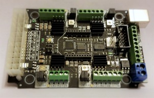
CNC xPRO Driver

Discussion in 'Other Builds' started by Spark Concepts, May 25, 2014.

  1. dean knipping

    Builder

    Joined:
    Mar 24, 2015
    Messages:
    84
    Likes Received:
    16
    Snokid...I have watched this and tried to translate it to the xPro but I am not finding a VREF test point on the board. I checked the schematics and did find A and BVREF which are pins 12 and 13 respectively on the driver chip and if I read the schematics correctly, it's going to the current limiting pot but doesn't show what solder point it is. I was able to ID the ground easy enough but that still leaves 2 points and the other issue is how tight it is in there and I don't want to slip and short anything out (wife already isn't happy with the bill)

    after watching the video again I figured I could do this by reading the current going to the drive just to find out that my cheesy POS meter doesn't read amps

    suggestions?
     
    #571 dean knipping, Aug 28, 2016
    Last edited: Aug 28, 2016
  2. Mark Carew

    Mark Carew OpenBuilds Team
    Staff Member Moderator Builder Resident Builder

    Joined:
    Jun 28, 2013
    Messages:
    2,763
    Likes Received:
    2,448
    This is something that is best discussed with the Part Store - http://support.openbuilds.com/support/home They are a great team and will take care of you to the best of their ability.
    Hope this helps and that you are cutting and carving soon.
     
  3. snokid

    snokid Journeyman
    Builder

    Joined:
    Oct 11, 2014
    Messages:
    335
    Likes Received:
    104
    you measure the vref from one of the solder tabs on the pot, can't remember which pad, but you won't damage anything if you test from ground to each pad.

    here's what spark concepts says about setting the current...
    Motor current set too low If motor current is set too low the motors will stall at speed, or even refuse to turn. Turn the motor current trimpot up (clockwise) until you get reliable motor operation.
    Motor current set too high If motor current is too high the stepper driver chips will go into thermal cycling, turning on and off slowly or even very rapidly. Back off the current until this stops.


    I have done it both ways, both work....
    but if you want to do it without a meter set the trim pot to the mid point, then go from there....
    warning....
    you should have heatsinks....
    If you set the current too high it might not show up till you run a longer gcode thru it.... I found this out the hard way. short gcode worked no problems then I cut a longer file and it went into thermo.....

    hope this helps....
    Bob
     
    Serge E. likes this.
  4. dean knipping

    Builder

    Joined:
    Mar 24, 2015
    Messages:
    84
    Likes Received:
    16
    ok thanks for the info...I will try setting it tonight from the solder pad. I do have a new meter coming though..you have to love amazon!
     
  5. Headlodius

    Builder

    Joined:
    Jul 31, 2016
    Messages:
    18
    Likes Received:
    5
    Thanks Mark, Looks like they will be helping me out!
     
    Mark Carew likes this.
  6. Headlodius

    Builder

    Joined:
    Jul 31, 2016
    Messages:
    18
    Likes Received:
    5
    Thanks I'll give it a try.
     
  7. Eric Schneider

    Builder

    Joined:
    Jan 10, 2016
    Messages:
    14
    Likes Received:
    0
    Hi, I'm having a problem with the limit switches on the XPro. I'm trying to set up the X and Y axes so that when the X or Y axis switch is tripped it will stop travel along that axis to avoid collisions with the end of travel. I have multi-metered my setup and the X-Axis limit pin (the one directly next to <X> MOTOR pin B1) does get connected to ground when I hit the X Axis limit switch. Travel along X and Y axes remains unchanged though. Any ideas on what is going on?

    Also, does anyone have details on what the behavior of the board is when tripping a limit switch? I don't know if the board disables all travel in that axis, disables only travel towards the switch, or just stops but doesn't disable motion. The Wiki information about the limit switches doesn't describe their behavior: 2. Connecting CNC xPRO · Spark-Concepts/xPRO Wiki · GitHub
     
  8. P.K.Hazell

    Builder

    Joined:
    Sep 21, 2016
    Messages:
    1
    Likes Received:
    0
    Hello,

    I have a CNC xPRO Driver (version 2) which was pre-loaded with GRBL version 0.9g. I am currently working on a project which requires me to alter the GRBL source code, however I only have the
    source code for GRBL version 0.9j. I have tried compiling this source code via Arduino IDE (using the instructions outlined on the webpage Compiling Grbl · grbl/grbl Wiki · GitHub) but got the error messages
    "avrdude: stk500_paged_write(): (a)protocol error, expect = 0x14, resp = 0x00" and "avrdude: stk500_cmd(): programmer is out of sync"

    I then tried using ATMEL Studio to compile the source code (again using the instructions outlined on the webpage Compiling Grbl · grbl/grbl Wiki · GitHub), then uploaded the hex file using Xloader, however I kept getting the error message "upload failed".

    I also have the precompiled hex file for version 0.9i and when I uploaded it to the board (via Xloader), I still got the error message "upload failed". I do not have this issue when I reload the 0.9g hex file.

    I was wondering whether anyone either had or could provide me a link to the source code for GRBL 0.9g, or knew why the board would not accept later versions of the GRBL code being uploaded to it?

    Thank you.
     
  9. yavor

    yavor New
    Builder

    Joined:
    Jan 17, 2015
    Messages:
    1
    Likes Received:
    0
    has anyone redone the grbl code so the xpro could be coupled with an lcd display via the SDA SCL pins? or is it even possible?
     
  10. Eric Schneider

    Builder

    Joined:
    Jan 10, 2016
    Messages:
    14
    Likes Received:
    0
    Does anyone know how the limit switches work? I've hooked it up so the limit switch pin gets connected to ground when the limit switch is clicked, as described in the hookup instructions, but the XPro motion is unimpeded by the limit switch connecting.
     
  11. Kevin Henning

    Builder

    Joined:
    Mar 18, 2016
    Messages:
    26
    Likes Received:
    3
    I've run into an issue with my xPRO (v2 version).

    When I initially set it up I connected using a 24V 400W LED power supply and communicated with it using a USB cable. Worked fine.

    Later I picked up an XBee format bluetooth module which uses the same RN-42 module that Spark-Concepts' BlueBee uses. With that I can communicate with the xPRO but can't drive the steppers attached to it. I hear some sound like they are trying to move, I can't turn them by hand, but no actual movement. However if I instead connect using USB things work fine.

    I verified that I am getting 24V into the xPRO.

    Has anyone seen this before and/or can offer some things I should look at? I am hoping to reduce the number of wires behind my machine.
     
  12. Spark Concepts

    Spark Concepts Journeyman
    Builder

    Joined:
    Dec 17, 2013
    Messages:
    131
    Likes Received:
    107
    P.K.Hazell - quick question - are you able to re-write the 0.9g hex file to the xpro?

    Eric Schneider - it sounds like your limit switch are wired and working properly - did you turn on Hard Limits in the GRBL setting? It should be command $21=1.

    Kevin - Is the bluebee you are running from us? If not, you likely need to adjust the baud rate (if you send me a link [email protected] I can get you some info on doing this)
     
  13. Spark Concepts

    Spark Concepts Journeyman
    Builder

    Joined:
    Dec 17, 2013
    Messages:
    131
    Likes Received:
    107
    Hi folks,

    With the release of the V3 board coming up, there have been a few good questions brought up that we thought should be addressed here in the support thread as well.

    1) Will the V3's work with all three motors offered at Openbuilds? A: The V3 is recommended for use on the standard Nema23's and Nema17's, the HT version will require more power than the DRV8825 can reliably produce
    2) Does the V3 still work with an ATX power supply? A: Yep, its one the favorite features and is not going anywhere
    3) Does the V3 still use the DRV8825 chips? A: Yep

    Please feel free to ask more questions if you have them! Thanks guys!
     
  14. anigeek65

    anigeek65 Well-Known
    Builder

    Joined:
    Sep 16, 2014
    Messages:
    57
    Likes Received:
    50
    This is interesting.. I am Using this board on 4 HT motors purchased from O.B. I haven't had any issues that I can tell. One small thing is that my "Y" axis, since it has two motors, it runs a Little noisy but still works fine. I have the controller mounted in a project box with are large fan to keep it cool. Are you suggesting I will have a failure soon using this board on these HT motors? Wish I had know this before I paired them up.
     
  15. Spark Concepts

    Spark Concepts Journeyman
    Builder

    Joined:
    Dec 17, 2013
    Messages:
    131
    Likes Received:
    107
    Hi Anigeek65,

    I should have expanded a little more on that - it's not that they wont work with the HT series, it's that the DRV8825s will produce 2.5A per coil while the HT series has a stall current of 3A per coil. All this really means is that your motors will not produce as much torque as the could with a 3A rated driver (that meaning they will stall before the rated torque load). I doubt you see any issue at all - I hope this helps answer your question.

    On a side note, if you would be interested in doing some beta testing please send me an email at - [email protected]

    Thanks,
    Mike
     
  16. anigeek65

    anigeek65 Well-Known
    Builder

    Joined:
    Sep 16, 2014
    Messages:
    57
    Likes Received:
    50
    Mike I sent you and email at the address provided. I got an automated response saying mailbox is full... Thanks.. Alan
     
  17. Spark Concepts

    Spark Concepts Journeyman
    Builder

    Joined:
    Dec 17, 2013
    Messages:
    131
    Likes Received:
    107
    Anigeek65, sorry about that I think our host went down during the black friday rush - should be all good now (or you could pm me here)
     
  18. anigeek65

    anigeek65 Well-Known
    Builder

    Joined:
    Sep 16, 2014
    Messages:
    57
    Likes Received:
    50
    Ok... Thanks Mike. I would be interested in beta testing. I have the v2 board for my build and I did realize when I bought it I would have reduced torque but was ok with it anticipating that I would not need the full torque of the HT motors. here is a picture of my build.. let me know what you would like me to do. I enjoy the O.B. site alot and enjoy the services they provide. Talk to you soon... Alan Ball
     

    Attached Files:

    MaryD likes this.
  19. Rob Mitchell

    Rob Mitchell Well-Known
    Builder

    Joined:
    Nov 29, 2015
    Messages:
    105
    Likes Received:
    35
    Hi Mike, I sent you a conversation request.

    Rob


  20. Whodare

    Whodare New
    Builder

    Joined:
    Jun 29, 2014
    Messages:
    3
    Likes Received:
    0
    Digger, I have a bunch of older 430 Watt AT PSU that I would like to use that have 20 pin connectors. The 12V rail on this PSU has 20A. I can't use the plug to connect to the board but if I cut all the wires and bundle all the yellow wires and black wires and connect to the 2 post side of the board (Opposite 24 pin connector) for 12V in (20A) that should work. I know i have to add a resistor to one of the red 5V wires to fool the PSU into thinking it has a load plus I have to isolate the Blue wire as the power switch. All other wires can be cut short and stowed off to the side. Can you see any other challenges I should look out for?
     
  21. Spark Concepts

    Spark Concepts Journeyman
    Builder

    Joined:
    Dec 17, 2013
    Messages:
    131
    Likes Received:
    107
    Whodare,

    don't cut it yet. The older style 20 pin plugs should fit if you insert like this .. 20161213_075945.jpg

    Let me know if you have any questions.

    Thanks,
    Mike
     
  22. Whodare

    Whodare New
    Builder

    Joined:
    Jun 29, 2014
    Messages:
    3
    Likes Received:
    0
    Thanks Michael, that helps but have a few more questions... SO, I plan use this board with the (3) NEMA17 motors that came with the bundle. At 1.68A apiece that makes 12V a little over 5A for max motor demand thru the connector. I plan to setup the push button switches/probe & emergency shut off switch and limit switches using the boards input power source ( I presume its 5V from the connector) into a small box off to the side of the cnc plate machine.That leaves the remaining wire to be cut short or available to be used for something else. Do you see any problems with me using the extra wire from the PSU for either 5V or 12V fans within the control box and or using them in a relay for lights or vacuum on/off switches?
     

    Attached Files:

    #592 Whodare, Dec 13, 2016
    Last edited: Dec 13, 2016
  23. Spark Concepts

    Spark Concepts Journeyman
    Builder

    Joined:
    Dec 17, 2013
    Messages:
    131
    Likes Received:
    107
    Hi Whodare,

    Just to make sure I understand correctly, you are asking if I see any issues with harvesting some of the aux plug wires for other uses? If so, I don't see a problem with it, just make sure to do it safely and you don't create shorts (or the possibility for shorts to happen).

    If I have misunderstood, please correct me.

    Thanks,
    Mike
     
    #593 Spark Concepts, Dec 16, 2016
    Last edited: Feb 6, 2017
  24. JonahD Green

    Builder

    Joined:
    Dec 17, 2016
    Messages:
    1
    Likes Received:
    0
    Using warm water allows the pores to
     
  25. jaserules

    jaserules New
    Builder

    Joined:
    Oct 10, 2016
    Messages:
    3
    Likes Received:
    1
    I have an Xpro v3 board , nearing the end of my oxmetal build and excited to get things running I have been held up buy problems and wondering if anyone has had anything similar regarding the cloned y axis stop working randomly, I have switch the y and clone motors and it changes to the different motor so suspect it maybe a setting or something to do with the board ...
    any help appreciated so I can move on to the next step ! Thanks

     
    Ernest Sutherland likes this.
  26. ChrisPhoto

    Builder

    Joined:
    Dec 26, 2016
    Messages:
    3
    Likes Received:
    0
    Will the
    CNC XPRO CONTROLLER V3 Will it mill in 3 D
    ATB Chris
     
    #596 ChrisPhoto, Jan 8, 2017
    Last edited: Jan 8, 2017
  27. gianakop

    gianakop New
    Builder

    Joined:
    Feb 27, 2015
    Messages:
    11
    Likes Received:
    20
    Spark Concepts and Mark Carew like this.
  28. Rob Mitchell

    Rob Mitchell Well-Known
    Builder

    Joined:
    Nov 29, 2015
    Messages:
    105
    Likes Received:
    35
    Has anyone upgraded to GRBL 1.x with V2 board? If so what is your experience. What changes / impacts are there to the board pinouts or otherwise?
     
  29. Eric Schneider

    Builder

    Joined:
    Jan 10, 2016
    Messages:
    14
    Likes Received:
    0
    @Michael thanks for your tip about the GRBL hard limits! Setting the hard limit $21 setting to 1 made the limit switches stop the system. Thanks a lot!
     
  30. ImagClaw

    ImagClaw New
    Builder

    Joined:
    Oct 20, 2016
    Messages:
    5
    Likes Received:
    0
    In the description on the openbuilds store the cnc xpro v3 states: "Laser Cutter With XY, Auto Focus, and Rotary Attachment". Has anyone actually done this and are willing to share their setup? I am really interested in making my c-beam model a dual purpose CNC/laser machine. Any replies would be great!
     

Share This Page

  1. This site uses cookies to help personalise content, tailor your experience and to keep you logged in if you register.
    By continuing to use this site, you are consenting to our use of cookies.
    Dismiss Notice