Welcome to Our Community

Some features disabled for guests. Register Today.

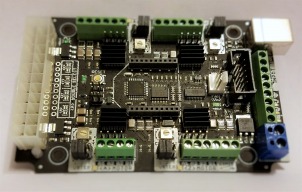
CNC xPRO Driver

Discussion in 'Other Builds' started by Spark Concepts, May 25, 2014.

  1. Richard Watson

    Builder

    Joined:
    Dec 28, 2016
    Messages:
    16
    Likes Received:
    2
    Hi Ryan
    Thanks for your reply
    no $4 is set to $0, I have all settings as per the photo supplied with the c-beam kit. C-Beam Machine GRBL Settings.JPG
     
  2. Ryan Lock

    Ryan Lock Veteran
    Builder

    Joined:
    Oct 12, 2014
    Messages:
    530
    Likes Received:
    294
    That could be the cause, on the new xPros $4 should be 1
     
    olecam likes this.
  3. sunil

    sunil New
    Builder

    Joined:
    Aug 16, 2016
    Messages:
    26
    Likes Received:
    11
    just a quick one.. anyone connected their xpro v2 to a vfd? as in control the speed of the spindle and turn/off too? i have a hy 2.2kw vfd but unsure of the output of the v2 and the vfd says it can take a signal of 0v to 10v.

    thanks in advance
     
  4. Kevin Henning

    Builder

    Joined:
    Mar 18, 2016
    Messages:
    26
    Likes Received:
    3
    I had a look at the xPRO wiki and it appears that the spindle output of the V2 is 0 to 5V.
     
  5. Ryan Lock

    Ryan Lock Veteran
    Builder

    Joined:
    Oct 12, 2014
    Messages:
    530
    Likes Received:
    294
    Yes this spindle output it 0-5v on the xPro, if you see this build description there is more info.

    Ryan
     
  6. Kevin Henning

    Builder

    Joined:
    Mar 18, 2016
    Messages:
    26
    Likes Received:
    3
    Michael, I have a question regarding a design decision that was made for the board. Specifically the ATX power on and A-motor sources; why did you go with a solder jumper for those rather than using a 0.1" header like is used for selecting the microstepping? I'm not too bad with a soldering iron (although I do admit to still occasionally wincing at the smell of my burning fingers :) but I do find that working with small pads like that a problem.
     
  7. Gary Caruso

    Gary Caruso OpenBuilds Volunteer
    Staff Member Moderator Builder

    Joined:
    May 19, 2016
    Messages:
    1,194
    Likes Received:
    534
    you want this converter then, amazon link
     
  8. Ernest Sutherland

    Builder

    Joined:
    May 30, 2017
    Messages:
    17
    Likes Received:
    3
    I have the exact same problem.
     
  9. Rick 2.0

    Rick 2.0 OpenBuilds Team
    Staff Member Moderator Builder Resident Builder

    Joined:
    Dec 20, 2013
    Messages:
    2,899
    Likes Received:
    1,556
    Cross referencing the post you referenced leads here which provides the answer you seek.
     
  10. olecam

    olecam New
    Builder

    Joined:
    Jun 6, 2017
    Messages:
    30
    Likes Received:
    6
    Hi -

    Thanks for pointing this out @ryan! I just finished my OX tonight and I really fretted over why I could not get the motors to turn, whatever I was trying. I have undo/redo all my wiring, checked again and again while it was just a setting!

    Well, that should probably be fixed in OX build instructions in order other guys not to face the same problem.

    --
    Olivier
     
    Ryan Lock likes this.
  11. jhubbs

    jhubbs New
    Builder

    Joined:
    May 25, 2017
    Messages:
    1
    Likes Received:
    0
    Does the V3 board have a solder jumper for using an ATX power supply with an external power switch (e.g. emergency stop button)?
     
  12. olecam

    olecam New
    Builder

    Joined:
    Jun 6, 2017
    Messages:
    30
    Likes Received:
    6
    Ahah I just found a folded sheet of paper in one of the box. Guess what? It is titled "Manual Amendment" and it gives instructions regarding the settings which are a bit different in the latest batch of CNC xPro. ;)

    Ryan: maybe you should insert it in the printed manual in order for the makers not to discover it after the kit is built and CNC is working! LOL :)

    --
    Olivier
     
    #702 olecam, Jul 12, 2017
    Last edited: Jul 12, 2017
  13. Ryan Lock

    Ryan Lock Veteran
    Builder

    Joined:
    Oct 12, 2014
    Messages:
    530
    Likes Received:
    294
    Hi,

    Yes i think we are going to change where we put it :thumbsup:

    Ryan
     
  14. olecam

    olecam New
    Builder

    Joined:
    Jun 6, 2017
    Messages:
    30
    Likes Received:
    6
    Hi -

    Sorry to rely to an old post but I'd like to have your help, if possible, regarding the Bluetooth module.

    I'm trying to get an RN42XV Bluetooth Module I just received from radiospares. I have successfully paired my computer to the module. I can enter Command Mode with my terminal emulator, send commands and I am able de see what the module sends back to me.

    But when I am in data mode (passthrough), I am not able to send commands to the xPro controller (commands are just ignored). I have connected a scope to pin 2 (TXD) on the RN42 module, and I can see a signal on that pin when sending orders from my computer. So I suppose that it is OK so far.

    In addition, I connect a computer on the USB port, I can see the data sent by xPro (GRBL initialization sequence and so on). So I think that speed/parity/... is correctly set, isn't it?

    I payed attention to set the baud rate to 115200 8N1 and to place a jumper between CTS and RTS according what Michael said. My xPro board is a V3.

    I haven't been able to find a schematic for the V3 board so it's not easy to follow the signal up to the atmega. Maybe is there something I have missed up? Any suggestion would be greatly appreciated. Thanks!

    --
    Olivier
     
    #704 olecam, Sep 8, 2017
    Last edited: Sep 8, 2017
  15. olecam

    olecam New
    Builder

    Joined:
    Jun 6, 2017
    Messages:
    30
    Likes Received:
    6
    Well, I did investigate further and I improved my understanding of the problem. Thanks to Kevin H. who sent me an email with some things to check.

    In fact the +5V is present only if the USB cable is connected. This is why the "Grbl 1.1f ['$' for help]" banner is shown always as soon as you connect the USB plug into the computer.

    When the USB cable is disconnected, VCC drops to ~3V and the voltage is very unstable / noisy: an IC has no chance to operate under these conditions. This is probably why I am not able to communicate with the atmega when usb cable is unplugged.

    So, for the atmega and other active components to work, it is necessary to plug the USB cable (either in a computer or in a phone charger). But in that case, data received through bluetooth no longer comes to the RX-I_FT line: I suspect that a high level is forced by the FT232 chip, which prevents bluetooth data to come in. I could probably get rid of that unsoldering FT232's pin 1, but I'm confident that another solution exists. Not so easy to confirm without a schematic unfortunately!

    PS: I not using the ATX connector, but the 12/24V input connector according to the manual of my ooznest machine.

    Regards,
    --
    Olivier
     
  16. olecam

    olecam New
    Builder

    Joined:
    Jun 6, 2017
    Messages:
    30
    Likes Received:
    6
    That's it: unsoldering pin 1 and the bluetooth module works as expected!
    Is this a bug in the xPro v3 or do I have made something wrong?

    --
    Olivier
     
  17. Spark Concepts

    Spark Concepts Journeyman
    Builder

    Joined:
    Dec 17, 2013
    Messages:
    131
    Likes Received:
    107
    Olecam,

    There is a 5V regulator on board. The irregular voltages on the 5/3.3V rails are typically due to input power noise or motor feedback. There are a couple easy ways around this:
    1) Add a >100uF capacitor to the 12V/24V input
    2) Use an ATX power supply (super clean power)
    3) Inject 5V to the board edge screw terminal

    Which chip did you remove pin 1 from?
    Also, schematic is here
     
  18. olecam

    olecam New
    Builder

    Joined:
    Jun 6, 2017
    Messages:
    30
    Likes Received:
    6
    Hi!

    The pin 1 I did remove is from what I was supposing to be an FT232!... You can certainly imagine my consternation when I discovered the schematic (thanks for that, Michael)! I was able to see data flow with my scope on that pin so I even did not consider that it could not be the TXD line!...

    BTW, I haven't been able to see where pin 1 (DTR) is wired to on the schematic. I probably need more coffee! ;)

    I'll investigate further regarding irregular voltages on VCC. Even the 5V LED shining is very unstable which attest to a real problem.

    Thanks and best regards,
    --
    Olivier
     
  19. olecam

    olecam New
    Builder

    Joined:
    Jun 6, 2017
    Messages:
    30
    Likes Received:
    6
    Ahah I feel like an idiot! o_O The pin I did remove is actually pin 20, not pin 1. :)
    It all adds up!...

    --
    Olivier
     
  20. olecam

    olecam New
    Builder

    Joined:
    Jun 6, 2017
    Messages:
    30
    Likes Received:
    6
    Hello again. I have checked the 5V regulator on board. The 24v input voltage is absolutely clean: no wavering, no noise. On C15, voltage was about 3v with oscillations.

    After that, for some reason I have damaged L2 (can't tell why, for fear of being discredited forever!). I have replaced it by a 10 ohms resistor. And guess what? The 5V is now perfect: rock stable, no more noise, no more wavering.

    I don't think it could also fix my bluetooth problem (I did not try to solder pin 20 again). Maybe I should try to put a jumper on a small board beside the xPro one. I'll wait a bit before doing anything in case someone has a better idea. :)

    --
    Olivier
     
  21. Garrett Groll

    Builder

    Joined:
    Aug 14, 2014
    Messages:
    54
    Likes Received:
    7

    Hi Michael!
    I'm wanting to buy the blueBee module, but I don't know which pre-configuration to select. I bought my xPRO V3 from OpenBuilds. How do I determine whether I need 115,200 baud or 9,600 baud? In your comment that I'm replying to, you told scooter that with sparkconcepts' blueBee module, it's basically plug and play. That's what I'm needing because all of that...wiring jumpers/parity/8-bits jibberish goes way over my head : ) I need plug and play lol!
     
  22. chuckd

    chuckd New
    Builder

    Joined:
    Sep 18, 2017
    Messages:
    10
    Likes Received:
    0
    garrett-groll - I also am interested in connecting with bluetooth Is it basically just handshake and start sending data?

    Also, is it possible to send gcode over ICSP header?

    It appears that ICSP is only for flashing the board in xPRO V3. Is the standard/factory installed grbl build allow for serial commands over these pins or is it possible with a custom build to expose those pins? The xPRO is not dedicated component in my setup so I dont have ability to use provided usb. I am using ATX to power the board.
     
  23. Ryan Turner

    Builder

    Joined:
    Mar 1, 2016
    Messages:
    68
    Likes Received:
    13

    I’ve been playing about with blue tooth on my prov2 too. I have the same issue that @olecam had. I tried using a XBee equivalent HC-06 ( slave only ) configured it for 115200 and soldered the jumper on. I put a capacitor across the 24 volt and the Bluetooth is discoverable. Any commands I send are ignored and I can’t read the Grbl settings at all.

    Now I can’t even get the XBee to talk on AT commands . Getting help from the local suppliers.

    It’s not really cost effective for me to order a blueberry from spark concepts. However I think I found a Blubee supplier in the UK for £15.
     
  24. olecam

    olecam New
    Builder

    Joined:
    Jun 6, 2017
    Messages:
    30
    Likes Received:
    6
    It is now almost 4 weeks that my CNC is controlled through my Microchip RN42XVP-I/RM Bluetooth.

    I did not try to solder back Pin 20 (DOUT) from FT231XS because the communication works as is.

    In addition, I never faced hang or freeze problems like I did in the past via USB, even with the Dewalt router under load. I think Bluetooth is a really something to consider! :)

    BTW, +5V is now 100% stable since I have removed L2: no more low frequency oscillations!

    Best,

    Olivier
     
    GrayUK likes this.
  25. Garrett Groll

    Builder

    Joined:
    Aug 14, 2014
    Messages:
    54
    Likes Received:
    7
    Nearly, everything you said went right over my head lol! Sorry I won't be much of help. I just sent my xPRO off to Spark Concepts, the company that makes the xPRO. They're going to do all of the bluetooth stuff for me seeing I can't tell my butt from a hole in the ground when it comes to electronics : )
     
  26. Firetruckguy

    Builder

    Joined:
    Aug 30, 2014
    Messages:
    23
    Likes Received:
    15
    I jut let the magic smoke out of the chip for my Z axis, not sure what I did. Everything was fine I had run several parts and was making a few modifications to the G code so I powered down my 24v power supply but did not unplug the USB. I came back about 15 minutes later hit the power switch and Pop!. from everything I can tell it's just the Z axis, it moves X and Y - and +. Anyone else have any similar issue? My board is a V2 Xpro. is it worth fixing or has anyone sent there board Spark to Spark Concepts for repair, a new V3 board is only $120
    IMG_9287.jpg
     
  27. RonD01

    RonD01 New
    Builder

    Joined:
    Mar 14, 2017
    Messages:
    5
    Likes Received:
    0
    This might not be the proper place for this, and it has probably been posted before, but any help would be appreciated. I am upgrading my motors to nema 23 with 425 oz.in requiring 4.2 amps. I have external drivers that will do the job from a previous setup, and the specs for this board state that "Step/Dir breakout pads to add external drivers.". I realize this probably requires going directly to the board, which isn't a problem, but I can't find anywhere that tells me or shows what pins or connections to make. If someone could kindly point me in the right direction, I would be greatful.

    Thanks
     
  28. Gary Caruso

    Gary Caruso OpenBuilds Volunteer
    Staff Member Moderator Builder

    Joined:
    May 19, 2016
    Messages:
    1,194
    Likes Received:
    534
    Personally I would not risk a $120 board when a $16 arduino Uno can do this, save the xPro for another project.. it's perfect for lower power more compact applications.

    Oh the pads are on the bottom..
    upload_2017-10-13_13-12-18.png
     
    #718 Gary Caruso, Oct 13, 2017
    Last edited: Oct 13, 2017
  29. RonD01

    RonD01 New
    Builder

    Joined:
    Mar 14, 2017
    Messages:
    5
    Likes Received:
    0
    Any help on the wiring sequence?
     
  30. Gary Caruso

    Gary Caruso OpenBuilds Volunteer
    Staff Member Moderator Builder

    Joined:
    May 19, 2016
    Messages:
    1,194
    Likes Received:
    534
    You would need to look at the driver(s) you have and RTFM ;)
     
    Peter Van Der Walt likes this.

Share This Page

  1. This site uses cookies to help personalise content, tailor your experience and to keep you logged in if you register.
    By continuing to use this site, you are consenting to our use of cookies.
    Dismiss Notice