Welcome to Our Community

Some features disabled for guests. Register Today.

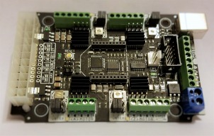
CNC xPRO Driver

Discussion in 'Other Builds' started by Spark Concepts, May 25, 2014.

  1. RonD01

    RonD01 New
    Builder

    Joined:
    Mar 14, 2017
    Messages:
    5
    Likes Received:
    0
    I have the documentation for the driver side, it's the xpro side I was looking for, smoothieboard shows an example and I thought maybe xpro did too.
     
    #721 RonD01, Oct 13, 2017
    Last edited by a moderator: Dec 6, 2017
  2. Kyo

    Kyo Veteran
    Staff Member Builder Resident Builder

    Joined:
    Feb 27, 2014
    Messages:
    673
    Likes Received:
    702
    The pins on the board look to be well labeled. The wiring really depends on the driver you have chosen. The driver manual should cover this in detail. On the X-pro v3 board photo Gary posted I see all the needed pins. 5v , gnd, enable, x y z dir, x y z step. I do not have a x-pro v3 board on hand to do a tutorial. But my uno + external driver "video" should give you a good start. Even if you want to use the X-pro in the final build. Pick up a uno to demo your wiring of the driver. It is a whole lot better to test on a cheap arduino then the x-pro.
     
  3. RonD01

    RonD01 New
    Builder

    Joined:
    Mar 14, 2017
    Messages:
    5
    Likes Received:
    0
    Thanks, the info will help a lot.
     
  4. Angus Shippey

    Builder

    Joined:
    Jul 20, 2017
    Messages:
    6
    Likes Received:
    1
    Hi Guy, another noob issue.
    When homing, my Z homes properly, i.e. touches the switch, reverses and then touches the switch again.
    X and Z touch the limit switch and don't reverse and touch the switch again.
    So they stop on the closed switch and lock the machine.

    I have double checked the wiring which is on the NC of the limit switch.

    Any ideas would be appreciated.
     
  5. RonD01

    RonD01 New
    Builder

    Joined:
    Mar 14, 2017
    Messages:
    5
    Likes Received:
    0
    I don't know what controller board you are using, but xpro has settings related to homeing and bouceback speeds and other things along these lines. Whatever controller board you are using, google the $ settings for that board and see if there are any that may pertain to your problem. xpro allows you to see them from the setting tab in grbl panel, don't know if that applies to all boards, but give it a try. I know this doesn't answer your question, but by checking on this you may stumble upon something that is useful.
     
  6. Peter Van Der Walt

    Peter Van Der Walt OpenBuilds Team
    Staff Member Moderator Builder Resident Builder

    Joined:
    Mar 1, 2017
    Messages:
    15,299
    Likes Received:
    4,360
    The XPRO runs stock Grbl, so all the documentation on the GRBL WIKI still applies. In this case, $27: Grbl v1.1 Configuration · gnea/grbl Wiki · GitHub
     
  7. Angus Shippey

    Builder

    Joined:
    Jul 20, 2017
    Messages:
    6
    Likes Received:
    1
    Thanks for your suggestions, I solved it with Homing pull off $27=10
    was originally $27=1
     
    Peter Van Der Walt likes this.
  8. Critical

    Critical New
    Builder

    Joined:
    Feb 9, 2017
    Messages:
    28
    Likes Received:
    14
    I'm at the first stage of this, quite frankly awesome quote! Hence my being here! :confused:
     
    Mark Carew and GrayUK like this.
  9. Blayne

    Blayne New
    Builder

    Joined:
    Jan 9, 2017
    Messages:
    1
    Likes Received:
    0
    Hey peeps, can anyone help ???
    ive had my ox cnc for a while now running grbl on a cnc xpro v3 board, it has limit/homing switches installed, im using bcbc as my commander program, untill 2 days ago everything has been working perfect, but now when i home my machine, my X axis MPOS coords are showing completely different values than 2 days ago, which i driving me nuts as its stuffed up my settings in bcnc. , from my understanding, you cant even program your MPOS coordinates so why the hell has it just randomly changed. previously it was telling me my X axis was at -589.989 after homing, but now it tells me its at -55 which now shows the x axis homed at the right hand side of the
    bcnc work area screen, when before it was the left, i am totally confused what has happened, can anybody out there help me please ?? im about to throw my cnc in the bin !!!!
     
  10. Ryan Turner

    Builder

    Joined:
    Mar 1, 2016
    Messages:
    68
    Likes Received:
    13
    Have you upgraded your GRBL recently? I always do a screenshot of my setting so that if something goes awry I can just pump those values back in.

    I too use bcnc, maybe you should try their forums too.
     
  11. davels

    davels New
    Builder

    Joined:
    Aug 29, 2017
    Messages:
    14
    Likes Received:
    1
    Hello, I got a xPro V3, I have check the wiki but if I understand correctly, it's still 0V to 5V?

    So if I want to connect my xPro V3 (using UGS platform) to my HuangYang VFD, I have to use a Voltage to PWM adapter/converter. Does this one is ok too? PWM to voltage module 0% 100% PWM converted to 0 10V voltage-in Integrated Circuits from Electronic Components & Supplies on Aliexpress.com | Alibaba Group

    Or this one : https://www.amazon.de/WINGONEER-Dre...=UTF8&qid=1511996976&sr=8-14&keywords=pwm+10v

    As I'm in Belgium I can't order the one on amazon.com (only amazon.fr or amazon.de)

    And what about the spindle direction? Currently, each time I start the VFD, I have to reverse the rotation. Sometimes I forgot and in counter clockwise turn the bit doesn't work very well lol
    So I would like to have it automatically... :)

    Thx in advance for your help

    Edit : On the HY VFD, the PD070 function allow several paramaters :
    • 0 : 0-10V
    • 1 : 0-5V
    • 2 : 0 -20mA
    • 3 : 4-20mA
    • 4: 0-10V, stacked 4-20mA exterior pulse of input
    So if put PD070 to 1 I could be able to connect the xPro the the VFD directly?
     
    #731 davels, Nov 29, 2017
    Last edited: Nov 29, 2017
  12. Ryan Turner

    Builder

    Joined:
    Mar 1, 2016
    Messages:
    68
    Likes Received:
    13
    I reckon that should work. It won’t do it any harm. It’s only to trigger a signal so the current draw on the xpro terminal will be minimal.

    Since the VFD says it accepts 0-10 v and the xpro termainal is 5 volts it should be fine. The worst that can happen is nothing will happen.

    If you were in the opposite situation where the xpro terminal was 24 volts and the vfd is 0-10 volts i’d Say NO!
     
  13. Ryan Lock

    Ryan Lock Veteran
    Builder

    Joined:
    Oct 12, 2014
    Messages:
    530
    Likes Received:
    294
  14. davels

    davels New
    Builder

    Joined:
    Aug 29, 2017
    Messages:
    14
    Likes Received:
    1
    I just try now and it partially work! The spindle doesn't start automatically, I have to push on the start button of the VFD, but I suppose it's "normal" because the direction isn't set/linked. Am I right ?

    About the speed, it works, but when I set 24000RPM in UGS, the spindle turn at 2880RPM. If I set it to 12000RPM in UGS, the spindle turn at 1440RPM ...
    I have check the output voltage of the xPro and at 24000RPM, it's 4.65V (seems to be the 5V output).

    I assume this is maybe a parameter in the VFD, does any one have any idea?

    The GND of the xPro is linked to ACM on VFD and the D11 on the xPro (V3) is linked to VI on the VFD.
     
  15. Ryan Turner

    Builder

    Joined:
    Mar 1, 2016
    Messages:
    68
    Likes Received:
    13
    I am
    Sounds like the ratio is out.

    I am not a huge fan of UGS or UGS platform. I initially thought it was one of the most stable senders but I am experienced a few issues and I found the number of buttons for various functions to be lacking.

    I now use bcnc and fine it much better and more reliable.

    I’m also going to have a go at using Estlcam ( you can trial the cnc for free ) but make sure you take down your grbl settings before you do because Estlcam uses custom firmware.

    I also fancied trying Easel but I don’t think there is enough functionality.
     
  16. davels

    davels New
    Builder

    Joined:
    Aug 29, 2017
    Messages:
    14
    Likes Received:
    1
    I'm a step further and now, the spindle RPM looks better. I can't only get close around few % of the rotation asked.
    Because of the 5V output voltage on the xPro V3 give 4.65V really.
    And the lower voltage is not 0 but 0.02V... so the spindle doesn't really stop.

    About the spindle direction, I switch U & V and it's working nice now... so simply! (saw it on on a website...)

    I'm thinking to maybe put an arduino between the xPro V3 and the VFD, so I could connect it throw RS485.
    How can I detect on the xPro V3 the command M3 or M5? Only if there is voltage on the D11?
     
  17. planga

    planga New
    Builder

    Joined:
    May 10, 2014
    Messages:
    23
    Likes Received:
    3
    So, I finally got my OX running (...only after a few years, Yeah!) with the CNC xPro v2. It seemed to be working for the most part. I was only having it move around, not cutting anything yet. The only issue I was having was that if I created a square with 1" sides and sent the gcode to the machine. It would trace a square approx 4 times as large and way out of place on the table (like 4 times the X and Y position where it should have been). Not sure what that was about, but anyway, I flashed the xPro with GRBL 1.1 thinking that that might be the place to start to fix the issue. I then modified some settings for the CNC OX based on what I saw here (5. Troubleshooting · Spark-Concepts/xPRO Wiki · GitHub). So now, after the re-flash, the machine will sit there and click every once in a while (motor(s) twitches), then one of the Y axis motors makes a quiet whine sound, whine up then whine down. This just repeats and jogging is not working as it was before the flash. I'm continuing to troubleshoot, but if anyone has any ideas, please let me know. Thanks.
     
  18. Spark Concepts

    Spark Concepts Journeyman
    Builder

    Joined:
    Dec 17, 2013
    Messages:
    131
    Likes Received:
    107
    Hi Planga,

    Congrats on finishing the build! Sorry to hear there is trouble abound...

    So the first issue sounds like the X and Y steps per mm seeing was off. Should be around 26.667 if you are using the default 8 microsteps setting.

    For the reflash issue: there was a bit of a communication packet change between 0.9 and 1.1, so you probably need to update your sender program (Universal Gcode Sender (nightly build) and GRBL Panel are good choices).

    If you have already updated your sender, check that your $4 setting is $4=0.

    If none of that helps, can you send your settings?

    Thanks
    Mike
     
  19. planga

    planga New
    Builder

    Joined:
    May 10, 2014
    Messages:
    23
    Likes Received:
    3
    I believe you may be right on the X and Y steps being off. Prior to reflashing I had not messed with the settings and I believe they were off (that's when I saw the sizing issue). I fixed them after the reflash, but haven't gotten the machine to run properly so I can see if the new settings work or not.

    I also have the latest (2.0 nightly build) of Universal Gcode Sender. $4=0 is what I have and microsteps are jumpered to 8. I have all Nema 23's and the 24v ps bought from the openbuilds parts store. I also have no limit switches hooked up yet (may get them hooked up over the weekend).

    Here are the machine settings (keep in mind I have xPro v2):
    $0=10
    $1=255
    $2=0
    $3=6
    $4=0
    $5=0
    $6=0
    $10=3
    $11=0.020
    $12=0.002
    $13=0
    $20=0
    $21=0
    $22=0
    $23=3
    $24=50.000
    $25=1200.000
    $26=25
    $27=5.000
    $30=1000
    $31=0
    $32=0
    $100=26.670
    $101=26.670
    $102=199.900
    $110=7500.000
    $111=7500.000
    $112=1500.000
    $120=150.000
    $121=150.000
    $122=150.000
    $130=510.000
    $131=770.000
    $132=170.000

    Thanks!
     
    #739 planga, Dec 15, 2017
    Last edited: Dec 15, 2017
  20. Spark Concepts

    Spark Concepts Journeyman
    Builder

    Joined:
    Dec 17, 2013
    Messages:
    131
    Likes Received:
    107
    Hi Planga,
    Nothing looks terribly out of place with the settings ($26 should be around 250 for when you put limit switches on, and you may try lowering the acceleration a little bit but 150 is typically good). Could you post or pm a short video of what happening? Do the work position/machine position update in UGS when you send a jog command?

    Thanks
     
  21. planga

    planga New
    Builder

    Joined:
    May 10, 2014
    Messages:
    23
    Likes Received:
    3
    Thanks MIchael. I did get it to trace a square today and it was the proper size. I didn't measure it exactly, but it looked right and was way better than the first time when it was approx. 4 times the size. So those settings definitely helped. I still have 2 issues and I will post a video tomorrow of the motor clicking then whining issue. The other issue is that about 50% of the time when I run the gcode for the square, it will not move the Y axis and I see some comments in the output that say something like "...command skipped". I had this issue prior to upgrading to gcode 1.1 and still have it (after upgrade). I'll provide details tomorrow when I post the video. Thanks again!
     
  22. Spark Concepts

    Spark Concepts Journeyman
    Builder

    Joined:
    Dec 17, 2013
    Messages:
    131
    Likes Received:
    107
    Can you upload your gcode file as well? How did you make the file?
     
  23. planga

    planga New
    Builder

    Joined:
    May 10, 2014
    Messages:
    23
    Likes Received:
    3
    Here is a video of the strange "click, then ramping up then down" sound. Might have to turn the volume up as the sound is kind of faint. My OX is using a CNC xPro V2. This happens after power up and doesn't matter if connected to Universal Gcode Sender or not. This started happening after the upgrade to GRBL1.1. After the initial click sound, the Y stepper motors are locked (can't be moved), then after the ramp up and down sound is done, they free up. Any ideas what might cause this or how to fix?

    Below, I've included the gcode for the issue I mentioned earlier. To recap: when cutting a small square, the router moves to the right on the X, skips moving down on the Y, moves left on the X, then skips moving up on the Y. So essentially, the Y axis does not move. However when I run this gcode, about 50% of the time the Y works fine. The gcode was produced from Sketchup/Sketchucam and I'm using Universal Gcode Sender on Windows 10.

    %
    (Generated by SketchUcam V1.4d-80c0152)
    (Bit diameter: 1/8")
    (Feed rate: 8' 4"/min)
    (Material Thickness: 1/4")
    (Material length: 3' 11" X width: 2' 8")
    (Overhead Gantry: true)
    (Plunge Depth first)
    (Optimization is ON)
    (Z ZERO IS TABLETOP)
    (www.PhlatBoyz.com)
    G90 G20 G49 G17 F100
    M3 S15000
    G00 Z0.375
    X0.3646 Y0.2085
    G00 Z0.27
    G01 Z0.0 F100
    X1.4896
    Y1.3335
    X0.3646
    Y0.2085
    G00 Z0.375
    G00 X0 Y0 (home)
    M05
    M30
    %
     

    Attached Files:

    #743 planga, Dec 18, 2017
    Last edited: Dec 21, 2017
  24. Spark Concepts

    Spark Concepts Journeyman
    Builder

    Joined:
    Dec 17, 2013
    Messages:
    131
    Likes Received:
    107
    @planga, sorry I missed see that this post was updated. I have looked aver everything and there shouldn't be any reason the V2's cannot be ran with GRBL 1.1f from a hardware perspective. Did you happen to try reverting to GRBL 0.9 and seeing if it worked? Do you have the HT series Nema23 motors or the standard?
     
  25. planga

    planga New
    Builder

    Joined:
    May 10, 2014
    Messages:
    23
    Likes Received:
    3
    Thanks Michael. The strange whining sound started after the upgrade to GRBL 1.1, so a downgrade to 0.9 could fix that, but the problem with the Y axis not moving occasionally was happening prior to upgrading to GRBL 1.1. I'll try to downgrade the GRBL to 0.9 to see if that fixes the whining sound, but I'll have to keep digging into the issue with the Y axis not moving. At this point, I might have to consider buying a new xPro board which would be a shame since I've never gotten this one to work properly.
     
  26. Spark Concepts

    Spark Concepts Journeyman
    Builder

    Joined:
    Dec 17, 2013
    Messages:
    131
    Likes Received:
    107
    Hi planga - I'm tracking now, I thought the issue was only when loading with 1.1 (apologies for the slow uptake on that one...). Don't buy a new one just yet - could you submit the linked contact page so I can get a formal trouble ticket in our system for you? Contact US
     
  27. CharlieShimota

    CharlieShimota Well-Known
    Builder

    Joined:
    Nov 11, 2017
    Messages:
    30
    Likes Received:
    41
    Hi, a newbie with a question. I just received the xPRO v3 along with 4 DQ542MA stepper drivers for my high-torque NEMA 23's. Could someone please run me through the process of setting motor current on the xPRO. Do these boards always come with the trim pots set on the second detent, is that a good starting point?.......Thanks

    024.JPG
     
    #747 CharlieShimota, Jan 4, 2018
    Last edited: Jan 4, 2018
  28. Gary Caruso

    Gary Caruso OpenBuilds Volunteer
    Staff Member Moderator Builder

    Joined:
    May 19, 2016
    Messages:
    1,194
    Likes Received:
    534
    Hi Charlie, You really don't want to use an XPro with DQ542MA's unless you already had the Xpro..
    The current will not be used from the xpro so you don't have to worry about it.
    the best thing would be to use the Xpro for another project and get an Arduino Uno and run GRBL (Same as XPro but $16)
     
  29. Peter Van Der Walt

    Peter Van Der Walt OpenBuilds Team
    Staff Member Moderator Builder Resident Builder

    Joined:
    Mar 1, 2017
    Messages:
    15,299
    Likes Received:
    4,360
    But if you only have the XPRO on hand, you totally can... The pinouts are clearly labelled. Current setting of the onboard drivers only set the Onboard drivers. The DQ542MA current is set directly on each DQ542MA - using the silkscreened tables on the front, and the DIP switches between the terminals
     
  30. CharlieShimota

    CharlieShimota Well-Known
    Builder

    Joined:
    Nov 11, 2017
    Messages:
    30
    Likes Received:
    41
    Thanks guys, when I ordered the xPRO I didn't realize it wasn't really set up for my drivers.:( No problem, the parts store is ok with returning it, Gary recommended the Arduino Uno. If anyone else has a favorite bob that works well with these DQ542MA's I'd like to hear from you.
     

Share This Page

  1. This site uses cookies to help personalise content, tailor your experience and to keep you logged in if you register.
    By continuing to use this site, you are consenting to our use of cookies.
    Dismiss Notice