Welcome to Our Community

Some features disabled for guests. Register Today.

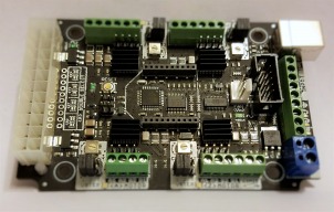
CNC xPRO Driver

Discussion in 'Other Builds' started by Spark Concepts, May 25, 2014.

  1. Gary Caruso

    Gary Caruso OpenBuilds Volunteer
    Staff Member Moderator Builder

    Joined:
    May 19, 2016
    Messages:
    1,194
    Likes Received:
    534
    I recommend getting a genuine arduino uno, and a screw shield like this one to make landing all the wires easy.
    Genuine Uno's seem to handle the data stream better than some clones.. I find genuine Uno's on ebay for $16-20 free shipping all the time.
     
  2. CharlieShimota

    CharlieShimota Well-Known
    Builder

    Joined:
    Nov 11, 2017
    Messages:
    30
    Likes Received:
    41
    Is this the board you're talking about? s-l500.jpg
     
  3. Spark Concepts

    Spark Concepts Journeyman
    Builder

    Joined:
    Dec 17, 2013
    Messages:
    131
    Likes Received:
    107
    @CharlieShimota: Yep thats the one - there are a few different flavors out there that you should look for (or look out for). The cheaper clones will run a CH340 serial chip that is an absolute headache to work with on faster data rates. Make sure the one you buy lists either the "16U2" or and "FTDI" chip set and you will save yourself a lot of frustration. If/when you add limit switches you will likely need to add some filtering or opto-isolation. There's probably more you could do but that should cover 99% of issues I can think of (and if it goes bad it is cheap to replace). If you need any help getting the firmware flashed shoot me a pm or an email ([email protected]) and I'd be happy to walk you through it.
     
  4. CharlieShimota

    CharlieShimota Well-Known
    Builder

    Joined:
    Nov 11, 2017
    Messages:
    30
    Likes Received:
    41
    Thanks Mike, I do plan on using proximity sensors, will they work with the Uno? What is filtering or opto-isolation? I will thank you in advance as I will surely be asking many more (probably dumb) questions.
     
  5. Giarc

    Giarc OpenBuilds Team
    Staff Member Moderator Builder Resident Builder

    Joined:
    Jan 24, 2015
    Messages:
    3,033
    Likes Received:
    1,695
    I would read the entire GRBL Wiki. It will help make sense of a lot of things. However, here are the ways to wire limit switches Wiring Limit Switches · gnea/grbl Wiki · GitHub. At this point I am using the capacitor for noise, but I may make one of the opto-isolation boards, or have a couple made.
     
  6. ClemC

    ClemC New
    Builder

    Joined:
    Aug 26, 2017
    Messages:
    7
    Likes Received:
    0
    maybe no longer watched (this feed is quite date) but I have the same question and found this on the web:
    not tested yet. WARNING this is for xpro v2 on the V3 the probe connectore are screw connectors betweenthe USB plug and the main power screw connectors
     
  7. Ryan Turner

    Builder

    Joined:
    Mar 1, 2016
    Messages:
    68
    Likes Received:
    13
    So I am posting those here because we all have the same board even though it’s only because of the board and not the ooznest kit.

    I’ve set up homing and soft limits and this works on the z and x axis.

    However.... The y axis only moves a short distance. I either get Alarm :9. Couldn’t find the limit switch within 1.5 x of the work distance. ( around 1250mm )

    Or

    it stops with in a short distance and just shows as having worked. I am not sure if it’s a false trigger or not.


    So, i’ve Reflashed the board, changed the homing direction, reinserted the distance, disconnected the limit switch on the y axis, moved the cables around away from the other wires. Disconnected the switch at the end of the wire and manually tripped it.

    Nothing makes any difference! Apparently the X Pro v2 has isolators on board so the only thing I can think of is the cable and or a grbl bug.


    By the way. It runs fine during normal ops with no homing or any kind of limit enabled. It doesn’t stall due to over heating. It’s grbl 1.1f.

    Suggestions?

    Thank you!
     
    #757 Ryan Turner, Jan 16, 2018
    Last edited: Jan 17, 2018
  8. daisosasen01

    Builder

    Joined:
    Sep 24, 2016
    Messages:
    58
    Likes Received:
    2
    Hello

    I know this is a very old post. But I am trying to get more tweaking info for my C-beam. Can you share your tweaks so I can get my machine not to sound so rough and loud? If you need any information from me I will be more then happy to provide what is needed. I am literally 1 day in after assembly and trying to iron out all the kinks ie: calibration etc to get it accurate and running like a lawn mower.
    Thanks
     
  9. Giarc

    Giarc OpenBuilds Team
    Staff Member Moderator Builder Resident Builder

    Joined:
    Jan 24, 2015
    Messages:
    3,033
    Likes Received:
    1,695
    How fast are you moving each axis? If they are moving real slow they will sound horrible, and loud.
     
  10. daisosasen01

    Builder

    Joined:
    Sep 24, 2016
    Messages:
    58
    Likes Received:
    2
    Hello all

    I finished assembling my C-beam machine. About to go thru the calibration process. Can anyone share their setting for me to start from?
     
  11. Spark Concepts

    Spark Concepts Journeyman
    Builder

    Joined:
    Dec 17, 2013
    Messages:
    131
    Likes Received:
    107
    daisosasen01 likes this.
  12. daisosasen01

    Builder

    Joined:
    Sep 24, 2016
    Messages:
    58
    Likes Received:
    2
  13. ClemC

    ClemC New
    Builder

    Joined:
    Aug 26, 2017
    Messages:
    7
    Likes Received:
    0
    Hi there,
    Not sure what you mean with the calibration process so I apologize for being quite broad and not so specific in this reply:
    • For the Gcode you may look at appendix 6.1 for the Ooznest manuel here.
    • For the Z azis zeroing, I use a touch plate linked to the Xpro like this one.
    • I've quicly added limit switches to have physical limitation and avoid messing up my material.
    Then for the calibration, I have drew a reticle on my base board, mount the mesh on the router and put it right in the spot manualy. Hit the Reset Zero and then use the touch plate to reset the Z axis. (this is good for laser printing or cutting (using the same point to the left down corner of the sheet to cut or print).

    NOTE: The calibration has to be in accordance with the job you want to do. If you want to mill on a 1 inch thick piece of wood or aluminium, make sure to set the Zero at 1 inch high in your milling program somewhere on the piece and then manualy zero your machine on the same spot. I put the touch plate on the piece, make the calibration for Z axis and deduct the thickness of the plate to set the Zero for Z.

    According to the thing I want to make, I usually prefer to set zero on the down (y) left (x) top (z) of the piece I mill and set the passes depth according to the material I'm miling (mdf, aluminium, foam, hardwood, etc).
    Sometime (e.g. circular pieces) I chose to calibrate the machine zero in the middle of the prime material, having previously set the gcode accordingly.

    You'll see, at the beginning, calibration sounds like a nightmare and after a few calibrations and recalibrations, It becomes a routine (which you should follow-up like a captain pre-flight checklist ;-)

    Enjoy your machine and, remember, only your imagination is now the limit !
     
    #763 ClemC, Feb 3, 2018
    Last edited: Feb 3, 2018
  14. Giarc

    Giarc OpenBuilds Team
    Staff Member Moderator Builder Resident Builder

    Joined:
    Jan 24, 2015
    Messages:
    3,033
    Likes Received:
    1,695
    Are you trying to calibrate it as in making it so it will cut exactly 100 mm when you tell it to? If so, you will need a ruler, calculator, and a v-bit if you have one. Your steps per mm are obtained from your microstepping of your driver, and belt/screw pitch.

    The steps/mm can then be calculated like this: steps_per_mm = (steps_per_revolution*microsteps)/mm_per_rev

    In my case with 1.8 degree stepper motors they were 200 x 8 microsteps / 12.7mm per revolution of my lead screws = 125.984251968504 steps/mm which goes into the $100, $101, and $102 settings

    Here is a poorly filmed video (by me) and the only redeeming values are that it is short and accurate. I get bored with long winded how-tos when they do not need to be. :thumbsup: I basically made it as part of documenting my CNC build and found it a quick reference I can post when people ask this calibration question. I guess I should have done a better job filming. 125.984 steps/mm was my starting point.

    Someone recently suggested putting it in the "Resources" section, so maybe I will.
     
    #764 Giarc, Feb 4, 2018
    Last edited: Feb 4, 2018
    GinoTheCop likes this.
  15. daisosasen01

    Builder

    Joined:
    Sep 24, 2016
    Messages:
    58
    Likes Received:
    2
    I got my machine running. After the first xpro v3 board was unresponsive I replaced it with a 2nd one I bought. (OPENBUILDS: what can I do about this? I purchased the board about 2 years ago and barely opened the package and connected it to my cbeam yesterday. Can I get store credit?)

    1) My problem, my X-stepper randomly stops moving when ordered to. Both manually and while executing a file. I read in the forums of a similar problem but don't recall which thread and the solution to it. All wires are connected properly. I have to disconnect the USB and the PSU and reconnect after to solve the problem which occurs again.

    2) I am having difficulty finding a software that is not ridiculously expensive. What I am trying to do is level a waste board and drill holes for counter sunk t-nuts. I have tried sketchup with sketchucam...and about to do fusion 360 but both are way complicated for the simple task I want.

    I created a custom waste board dimension of 360L x 360W to accommodate the cuts I want to do.
    Anyone able to help?
    (I am actively searching for answers by reading threads and using the search function. So far search results are not helpful)
     
  16. Gary Caruso

    Gary Caruso OpenBuilds Volunteer
    Staff Member Moderator Builder

    Joined:
    May 19, 2016
    Messages:
    1,194
    Likes Received:
    534
    I would guess your current setting is too high causing the stops, try dialing the current down a bit.
    As for software there are a bunch of free or nearly free ways to go, I started out using sketchuCam and UGS.
    But now I use a free 2D drafting program called Draftsight, it's just like Autocad 2004 that I was very used to and I now use Estlcam for my cam and for gcode sending, very happy with it.
    To level a spoil board, just create the shape and make a pocket for the area. In sketchucam, you can do the level in one file then any hole drilling in another file, different tools too.
     
  17. daisosasen01

    Builder

    Joined:
    Sep 24, 2016
    Messages:
    58
    Likes Received:
    2

    I just purcahsed a license for Estlcam. Is it possible to do a face chat thru facebook? I am a newbie and CAM/CAD eliterate. Some help would greatly be appreciated. I learn from being taught rather then reading and watching videos. if you can you can find me with my email [email protected]
     
  18. Giarc

    Giarc OpenBuilds Team
    Staff Member Moderator Builder Resident Builder

    Joined:
    Jan 24, 2015
    Messages:
    3,033
    Likes Received:
    1,695
    I know you said you prefer being taught, but why not just try cutting simple objects out of scrap using Estlcam. Also, I believe you need to make something using CAD software (Fusion 360 or Sketchup, for example) then import that object as an STL, DXF, etc file to start the CAM in Estlcam. Go into Sketchup and make a simple square the thickness of whatever scrap material you have and draw a few holes in it. Export it as an STL, then import it into Estlcam. You will need to enter information into Estlcam regarding what size and type of endmill you choose. Also, if you want parts cut accurately, you will need to measure the diameter of the endmill with a caliper. Not all 1/8 inch endmills are exactly 1/8 inch. Especially cheap ones.

    If I were trying Estlcam as a new person to CAM, I would draw the item in this video in Sketchup, do as I mentioned above, then practice exactly what the creator of Estlcam is doing in the video. No matter what, you will need to learn how to use CAD software to create original things. Fusion 360 has great instructional videos and so does Skecthup/Sketchucam. If you can't use those to learn - as you mentioned in your post above - then I would enroll in a class at a community college.
     
  19. daisosasen01

    Builder

    Joined:
    Sep 24, 2016
    Messages:
    58
    Likes Received:
    2
    After spending a day on fusion 360 I was able to make a wasteboard for the C-Beam. wasteboard 02-09-18 | Fusion 360 | Autodesk Knowledge Network
    My new problem is getting my C-Beam to start working. I am having difficulty with the probe I have. I wired the probe according to this picture from openbuilds. http://www.vslot-europe.com/127-thickbox_default/cnc-xpro-controller-stepper-driver-v3.jpg
    The ground being the aligator clip (red wire) for the drill bit and probe for the aluminum piece (black wire) that rests on the wasteboard. I'm using bCNC at the moment, and according to this youtube video
    I enter a negative value for the probe Z and click on probe. The machine is suppose to cycle and stop when it touches the probe. What it does instead is go down to reach the negative Z value I entered. Even when it touches the probe the machine continues till it reaches that negative value then I get an error message "Probe failed". Yea obviously it did...but I don't know why...
     
  20. daisosasen01

    Builder

    Joined:
    Sep 24, 2016
    Messages:
    58
    Likes Received:
    2
    And now my X-axis motor is not working....This machine is beginning to get under my skin....
    I used the higher voltage (but not all the way as recommended) and the X-axis motor is not working....I have no idea why it was working fine after replacing the Xpro board. @OpenBuilds I think you and I will need to talk...this is becoming way out of hand. I've tried to set this machine up for the last year. Now when I feel I'm at a point where I can start cutting the parts don't work...What gives?
     
  21. Ryan Turner

    Builder

    Joined:
    Mar 1, 2016
    Messages:
    68
    Likes Received:
    13
    Firstly check you z probe wiring by just getting the ends of the wires and touching them together and seeing if it stops.
     
  22. Ryan Turner

    Builder

    Joined:
    Mar 1, 2016
    Messages:
    68
    Likes Received:
    13
    On my v 2 I had an issue where one of my y axis motors would just stop working randomly. Replaced the board all was fine. Msg spark concepts. He’s very helpful.
     
  23. khalid tubail

    Builder

    Joined:
    May 13, 2014
    Messages:
    6
    Likes Received:
    1
    dear Michael
    I ordered OpenBuilds MiniMill with Nema 23 and 24v power supply.
    I installed, its look very nice.
    I had CNC xPRO Driver v2.
    when I connect the stepper motor to the driver, it's become overheat.
    as I checked later the CNC xPRO Driver v2 is peak current 2.5 A, and the Nema 23 is 28 A.
    is this setup is ok or I need to change the driver of the motors.

    regards
     
  24. ProAce

    ProAce New
    Builder

    Joined:
    Jan 23, 2017
    Messages:
    1
    Likes Received:
    0
    I received my CNC xPro v3 and to test it I connected one Nema 23 stepper and a power supply (24v). When I turned it on the LED's lit up, and the stepper started screeching. Before I could pull the plug smoke erupted from the board. What could I have done wrong? I'm certain that I hooked it up correctly.
     
  25. Spark Concepts

    Spark Concepts Journeyman
    Builder

    Joined:
    Dec 17, 2013
    Messages:
    131
    Likes Received:
    107
    Hi Khalid, you should be ok with the current setup - we run the same all the time. A few things though - 1) if you dont need the motors locked all the time, dont do it. locking the motors takes a lot of current and generates a lot of heat. Set $1 = 25 (grbl V1.1). 2) Use a PC fan to keep the board cool and make sure if it is in an enclosure that there is air flow. 3) you might need to adjust the current on the motor drivers down a little bit to keep them from overheating. Let me know if you have questions on any of this

    ProAce - well thats not the intended function of the board :blackeye:.... Could you email me so we can start a trouble ticket and get this sorted for you ([email protected])?
     
  26. bernabap

    bernabap New
    Builder

    Joined:
    Oct 25, 2014
    Messages:
    2
    Likes Received:
    0
    Hi there,
    first I would like to thank user olecam for his findings about the bluetooh problem, it saved me lot of time. This week I tried to use my bluebee from SparkConcepts but got same problem described by him, no matter what no command was sent to my board (kickstart batch). I agree with him that there is some problem with the TX-0_FT/RX-I_FT lines "occupying" the DOUT/DIN bluebee lines. Olecam said that unsoldering pin20 solved the problem. I have no idea how he made that, seems a very difficult job to unsolder just one pin from ftdi, and as this would make USB unusable, I found another route. I noticed that the board has a SPDT switch for the atmega TX-0/RX-I lines called (uart_ss) serial select. So I just used (applied 5v to) that switch to disconnect TX-0_FT/RX-I_FT and connect TX-0_IDC/RX-I_IDC to TX-0/RX-I. Then I used IDC lines for BT and all worked as expected. I also had to follow Michael instructions about the 5v line, as I am NOT using an ATX power supply, I did had to inject 5v to the board to communicate with atmega. At the end I just replaced my bluebee by an HC05 to fit inside my case.

    IMAG0856.jpg
     
  27. Ryan Turner

    Builder

    Joined:
    Mar 1, 2016
    Messages:
    68
    Likes Received:
    13
    I’ve bought an ATX PSU and have a RN42 BT module too.

    I went down the Xbee route but it stopped working. I got the Bluetooth connected with the RN42 and the 24v PSU but GRBL kept sending the initisation over and over and I assume the power wasn’t stable enough and it kept rebooting.

    I will report back with findings if it’s more stable with the ATX. Unfortunately this means either moving the board off the back of the ox and into a box ( placed there in the ooznest kit ) or mounting the ATX on the gantry.
     
  28. bernabap

    bernabap New
    Builder

    Joined:
    Oct 25, 2014
    Messages:
    2
    Likes Received:
    0
    Ryan, you don't need ATX power supply, just add an LM2596 to step down your 24v to 5v and inject that to the 5v terminal. I have done that and works fine.
     
  29. ClemC

    ClemC New
    Builder

    Joined:
    Aug 26, 2017
    Messages:
    7
    Likes Received:
    0
    Hi there,

    on V2 the probe pin is in the little brown pin block (check on Youtube: )
    on V3 (as below) the Z probe is on the side between the reset and the spindle direction.


    [​IMG]
     
  30. Ryan Turner

    Builder

    Joined:
    Mar 1, 2016
    Messages:
    68
    Likes Received:
    13
    Cool. An ATX is a bit neater though.
     

Share This Page

  1. This site uses cookies to help personalise content, tailor your experience and to keep you logged in if you register.
    By continuing to use this site, you are consenting to our use of cookies.
    Dismiss Notice