Welcome to Our Community

Some features disabled for guests. Register Today.

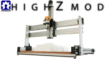
High Z Mod for Lead CNC

Discussion in 'CNC Mills/Routers' started by Mark Carew, Oct 11, 2019.

  1. Giarc

    Giarc OpenBuilds Team
    Staff Member Moderator Builder Resident Builder

    Joined:
    Jan 24, 2015
    Messages:
    3,015
    Likes Received:
    1,680
    Yes I do. I will put it in the files section of the lathe build as a .dxf when I get to my computer.
     
  2. Giarc

    Giarc OpenBuilds Team
    Staff Member Moderator Builder Resident Builder

    Joined:
    Jan 24, 2015
    Messages:
    3,015
    Likes Received:
    1,680
    Actually, it looks like it is here as the backer plate in the files tab. LEAD Lathe
     
  3. Jdubster3d

    Builder

    Joined:
    May 22, 2019
    Messages:
    61
    Likes Received:
    13
    Awesome thanks for your help...have you been running your cnc with the new setup? If so anything you would have done diff? Thanks again
     
  4. Giarc

    Giarc OpenBuilds Team
    Staff Member Moderator Builder Resident Builder

    Joined:
    Jan 24, 2015
    Messages:
    3,015
    Likes Received:
    1,680
    No. I have got distracted by building the LEAD Lathe. I am finishing that up now. I started assembling the new CNC with those modifications, but the build relies on me completely disassembling my current ACME OX (A Lead Screw Driven Ox Derivative (850x1500)) because I plan to reuse the Y axis 1/2-10" precision ACME 5 start lead screws and all the other components I purchased minus the extrusions. Those will be going to modify a K40 CO2 Laser. So, before I disassemble it, I need to be sure I have all the plates cut - which I know I do not.
     
    Jdubster3d likes this.
  5. Jdubster3d

    Builder

    Joined:
    May 22, 2019
    Messages:
    61
    Likes Received:
    13
    Sweet man good luck with that! Thanks for the info
     
  6. Makoto cameron

    Builder

    Joined:
    Nov 11, 2020
    Messages:
    29
    Likes Received:
    8
    Aloha
    New builder/ operator here, just finished building the Lead 1010 with the high Z mod. Movement is all correct (directions), but when i lower the Z high to the material i getting a fault error 15- jog exceeds machine travel. Command ignored, and also error 9 g code locked out during alarm or jog state. Im assuming that the controller assumes the standard Z high, i also assume this is corrected in gcode setting?
    Mahalo (thanks in advance)
     
  7. Peter Van Der Walt

    Peter Van Der Walt OpenBuilds Team
    Staff Member Moderator Builder Resident Builder

    Joined:
    Mar 1, 2017
    Messages:
    15,049
    Likes Received:
    4,313
    Did you remember to update Z Max Travel in Grbl settings with the longer available Z travel?
     
  8. Makoto cameron

    Builder

    Joined:
    Nov 11, 2020
    Messages:
    29
    Likes Received:
    8
    aloha
    no I did not, that's what I need to know how to do, sorry I'm new to this
     
  9. Makoto cameron

    Builder

    Joined:
    Nov 11, 2020
    Messages:
    29
    Likes Received:
    8
    #132 z axis max travel mm
    set to 500mm for the high Z mod?
    also should I change the y and x? currently at 200mm
     
  10. Peter Van Der Walt

    Peter Van Der Walt OpenBuilds Team
    Staff Member Moderator Builder Resident Builder

    Joined:
    Mar 1, 2017
    Messages:
    15,049
    Likes Received:
    4,313
    Measure the actual travel distance. 500 - 125 for the plate - offset for limit switch - some clearance of 1-2mm before it crashes into the bottom plate.

    If you want to use soft limits, yes.

    Read the entire Grbl wiki at github.com/gnea/grbl/wiki - it explains all this and much more - goldmine of info that will greatly ease your learning curve :)
     
  11. Makoto cameron

    Builder

    Joined:
    Nov 11, 2020
    Messages:
    29
    Likes Received:
    8
    thank you for your help Peter, yes I have looked at the gnea,grbl wiki but it will need reading and rereading to understand, as I said I am new to all this
     
  12. Makoto cameron

    Builder

    Joined:
    Nov 11, 2020
    Messages:
    29
    Likes Received:
    8
    this forum is tons of help
     
  13. Allistar

    Allistar New
    Builder

    Joined:
    Aug 19, 2019
    Messages:
    57
    Likes Received:
    19
    How heavy is that water cooled spindle? It looks like it's 80mm diameter, so 2.2kW? Is that the ER20 collet or ER11? So many questions I know! I want to know if I can put a 2.2kW (5.3kg) spindle on the Lead1515 with the high Z mod without it flexing.
     
  14. ClaudeJER

    ClaudeJER Well-Known
    Builder

    Joined:
    Oct 2, 2018
    Messages:
    39
    Likes Received:
    27
    I have the 1.5kW with ER11 collets. I did not weigh it but this information should be available from the vendor.
     
  15. Itchytweed

    Builder

    Joined:
    Feb 22, 2021
    Messages:
    22
    Likes Received:
    14
    I am stuck in a "if not this, what about this" issue with this mod. I have the configuration modifications done on paper for the z-axis movement based on what I am interested in doing. The z-stepper and leadscrew can handle either weight with ease. The main question is this: What is the max weight the configuration will handle for a spindle motor? I am looking at one of two spindle motors - one weighs in at 7 lbs / 800 watts and can handle 1/4" shanks and the other is 12 lbs / 2.2 kW that can handle up to 1/2" shanks.

    Thanks in advance.
     
  16. Peter Van Der Walt

    Peter Van Der Walt OpenBuilds Team
    Staff Member Moderator Builder Resident Builder

    Joined:
    Mar 1, 2017
    Messages:
    15,049
    Likes Received:
    4,313
    2.2kw is way overkill for an extrusion based machine, not only weight but also on the ability of the frame to resist the cutting forces, you'll never be able to utilise the 2.2kw because the frame would deflect before you are putting that much power through the cut. 800w is a nice sane size, lighter too.
     
  17. Itchytweed

    Builder

    Joined:
    Feb 22, 2021
    Messages:
    22
    Likes Received:
    14
    Thank you for the advice. I was thinking of the same thing but I wanted verification. 800 watts will allow for milling aluminum at slow, sane rates but the rigidity needs to be there to minimize edge chatter. Plus, the added stability would come from doing the work on the edge rather than in x-axis mid span. Now to pull the switch.......
     
  18. Alex Chambers

    Alex Chambers Master
    Moderator Builder

    Joined:
    Nov 1, 2018
    Messages:
    2,783
    Likes Received:
    1,364
    When you get to that point lubricant/coolant (I use meths) and a jet of air help a lot when milling aluminium.
    Alex.
     
    Itchytweed likes this.
  19. BeeAMaker

    BeeAMaker Well-Known
    Builder

    Joined:
    Apr 19, 2016
    Messages:
    122
    Likes Received:
    31
    Can I get this at 300mm on the Z instead of the 500?
     
  20. Rick 2.0

    Rick 2.0 OpenBuilds Team
    Staff Member Moderator Builder Resident Builder

    Joined:
    Dec 20, 2013
    Messages:
    2,892
    Likes Received:
    1,551
    Custom cuts on the extrusion are generally not a problem for the part store. Just put a message on the order as to what you need.
     
    BeeAMaker likes this.
  21. Allistar

    Allistar New
    Builder

    Joined:
    Aug 19, 2019
    Messages:
    57
    Likes Received:
    19
    I've just completed the build of my lead 1515 with the high Z mod (everything apart from the spindle, that's on back order). I've been tuning it and can get the Y axis to travel at 4000mm/min, though the X axis can only go 3000mm/min. Just before the stepper binds there's a resonant vibration around the x gantry. I tried very hard to get the two X axis C-beams parallel. There's a 0.3mm drop across the 1500mm span. I think it'll be difficult to get it closer than that. I have the slave X gantry about 8mm below the driven gantry.

    What would cause a mechanical bind at high speed? Could this be the lead screw nuts? I have lubed it with PTFE oil. Looking at the design it would seem that the slave gantry may "lag" behind the driven gantry and cause a twisting. Though both gantries are tightly coupled to the Y axis C-beam which should be a rock solid connection.

    I'll try connecting the back of the two gantries together to make them more rigid.

    Is it possible to run two X axis steppers so the lower slave gantry is also driven? Can the XPro V5 drive 5 steppers like this?

    Does anyone have ideas on how to prevent this binding, and hence be able to run X as fast as Y?
    Thanks,
    Allistar.
     
  22. Peter Van Der Walt

    Peter Van Der Walt OpenBuilds Team
    Staff Member Moderator Builder Resident Builder

    Joined:
    Mar 1, 2017
    Messages:
    15,049
    Likes Received:
    4,313
    Where was the mechanical kit purchased from?
     
  23. Allistar

    Allistar New
    Builder

    Joined:
    Aug 19, 2019
    Messages:
    57
    Likes Received:
    19
    Hi Peter,
    I bought it from makerstore.com.au (it's much faster and cheaper to buy it from there as I live in New Zealand).

    Thanks,
    Allistar.
     
    Peter Van Der Walt likes this.
  24. Peter Van Der Walt

    Peter Van Der Walt OpenBuilds Team
    Staff Member Moderator Builder Resident Builder

    Joined:
    Mar 1, 2017
    Messages:
    15,049
    Likes Received:
    4,313
    Just double checking, unofficial parts could lead to binding/misalignment issues.
     
  25. Allistar

    Allistar New
    Builder

    Joined:
    Aug 19, 2019
    Messages:
    57
    Likes Received:
    19
    Are the parts from makerstore.com.au are unofficial? They do claim to be a distributor of OpenBuild product.

    Can you confirm how tight the wheels should be? I have another CNC machine which has skateboard bearings running on stainless steel pipe. When the lead screw is disconnected I can push it and it'll gently roll to the end of the pipe with very little friction, and the slop in it is negligible. With the Lead 15 15 I can't do that. I can roll the gantry by pushing it but when I let go it immediately stops. Should it be able to roll freely? I wonder whether having the eccentric nuts too tight could cause this.
     
  26. Peter Van Der Walt

    Peter Van Der Walt OpenBuilds Team
    Staff Member Moderator Builder Resident Builder

    Joined:
    Mar 1, 2017
    Messages:
    15,049
    Likes Received:
    4,313
    No should be good, was expecting a more far east source maybe

    It should roll easy, but not too freely. I don't have experience with your controller, wondering if its not just stalling because of that. The ESP32 grbl timing is not as tight as official Grbl, so could jitter enough to stall at higher feedrates. But thats a wild theory I cannot prove (just gut feel) - have you played with the stepper driver settings? Not sure how much they allow you to change, but disabling things like StealthChop may improve speed
     
  27. Allistar

    Allistar New
    Builder

    Joined:
    Aug 19, 2019
    Messages:
    57
    Likes Received:
    19
    Thanks for your help. The binding is definitely mechanical in nature, I can tell it's going to bind at the X gantries get a build up of what sound like resonance, like they're being forced to move in a way they don't want to. The noise is like a high pitch squeak that gets stronger. I suspect I have the wheels too tight. I'll loosen them off a bit and will see if that improves things.

    I've been cutting air with a large gcode file that does a vcarving (one of the Aztec calendars that's been going around). This has a lot of very small movements and the Z axis moves up and down quite a lot. Even without a spindle it's noisy! Granted, I still have most of my tools scattered over the table, and it is sitting on a table tennis table which isn't super rigid. The steppers seem to bark at particular speeds. The movement is quick (350mm/s^2 acceleration) and it's not losing any steps. Is this kind of noise from these stepper normal? Will changing the microstepping from 8 to something else help this?
     
  28. Itchytweed

    Builder

    Joined:
    Feb 22, 2021
    Messages:
    22
    Likes Received:
    14
    I have a mod idea to the Z-axis actuator in mind to support my spindle. I have it worked out on paper but I have one question left. My plan uses a hole modified C-beam XL gantry plate to be bolted to the C-beam using low-profile screws through the gantry and t-nuts in the slots to catch the bolts. What I need is a verification of the screw length needed. The plate is 6mm thick. So I believe that I will need the M5x10 screw size. Am I correct in this belief?

    Thank you in advance.
     
  29. MrKenSan

    MrKenSan New
    Builder

    Joined:
    Mar 9, 2021
    Messages:
    19
    Likes Received:
    1
    Hi Folks, just getting started building a modified version of the LEAD 1010. Been working in CAD so far to tune things in to the dims required for this setup.

    One question we've punted on so far, but now coming to, is the Z-Axis. I note the "HighZ" mod, and the extra components required. A couple Q's 4 Y'all...

    1. In terms of "stiffness" (we'll be cutting Aluminum) how much is this increased by adding the second beam and carriage? Or put another way, how much twist/flex does the single C-beam gantry exhibit? What we're wondering is how much overall stiffness is gained, vs the single-beam gantry. Some "quantitative" metrics would help us to understand the trade-offs.

    2. I've read elsewhere that part of the rationale for the particular design of the HighZ mod is that it uses components already in inventory. Are there any community thoughts about perhaps condensing the design a bit by creating a single 160mm carriage plate, and only 2 sets of wheels? From the designers, what might the pros/cons be of such a design? (we don't need as much travel as the stock mod provides, but perhaps more than the "standard travel") Seems like it's always the "outside" wheel set that is going to be taking the bulk of the lateral load.

    3. To enhance X-Beam stiffness, has anyone considered an orthogonal beam to the X-carriage beam, or adding another beam to create a "laminated" beam? Again, would require some re-thinking of the design, but may perhaps add some stiffness with less height. This question is really more exploratory... Again, looking to the designer of the mod, or others who have experience with this and those who cut Aluminum with this type of machine.

    For background, we're looking at this both for our own use right now as a prototyping tool, but also perhaps more generally as part of our project to enable others. Won't bother folks here now with details of that except to say we'd be able to "optimize" the design for our use case because we'd be making quite a few (of the router systems).

    Thanks for your help and insights as we work to tune this in!
     
  30. MrKenSan

    MrKenSan New
    Builder

    Joined:
    Mar 9, 2021
    Messages:
    19
    Likes Received:
    1
    Hello Again Community!

    A follow up to the last question we posed...

    Has anyone looked into rotating the X-Axis C-beam by 90-Degrees? This would change the orientation of the X-Axis carriage, of course, so a little cleverness would be required for mounting Z, but with this, one gets a bit more clearance, and also the added stiffness of pushing against the C-Beam in its strongest axis. The Y-Axis is by far the "strongest" axis in terms of its ability to exert force when cutting (two motors driving, vs. 1 on the other axes), hence it may be beneficial to have the X-Beam be oriented in its stiffest orientation to resist flex in this direction.

    Added Benefit to this orientation is that forces against the bearings in the wheels of the X-Axis are in the "correct" direction. As designed/implemented, there is a lateral load on these bearings, which may cause premature wear. With the rotated X-Axis beam, it would then be the Z-Axis presenting lateral load onto the X-Axis bearings. The Z-Axis is likely to see the smallest loads, since one can't "force" a cutter into the material they are cutting.

    If someone has tried or thought about this, we'd love to learn from you. We'll noodle on it a bit here as well from a design perspective, but wanted to check in with the community to see if this had been considered & discarded for some reason which we're not immediately seeing.

    Much thanks!!
     

Share This Page

  1. This site uses cookies to help personalise content, tailor your experience and to keep you logged in if you register.
    By continuing to use this site, you are consenting to our use of cookies.
    Dismiss Notice