Welcome to Our Community

Some features disabled for guests. Register Today.

Maximus 3D Printer

Discussion in '3D printers' started by mytechno3d, Jul 16, 2014.

  1. Val Cocora

    Val Cocora Well-Known
    Builder

    Joined:
    May 19, 2014
    Messages:
    172
    Likes Received:
    28
    I have been using AutoCAD since 1990, hard to teach an old dog like me a few new tricks. Regarding the scaling up or down, I totally agree: I am in the process of building a printer with 1 cubic meter printable area (well, it's a little over that) using openbuilds v-slots and hardware.
     
  2. Val Cocora

    Val Cocora Well-Known
    Builder

    Joined:
    May 19, 2014
    Messages:
    172
    Likes Received:
    28
    indeed, however limited its practicality may be. my cnc guy would laugh at seeing four digits after the decimal separator.
     
  3. dwm.cadman

    Builder

    Joined:
    Feb 14, 2015
    Messages:
    2
    Likes Received:
    0
    Has anyone created SolidWorks or other CAD files for this build yet? I'd be glad to help.
     
  4. Mauricio Solid

    Builder

    Joined:
    Feb 17, 2015
    Messages:
    30
    Likes Received:
    12
    Hi Funk,,did you finally got the solidworks drawing done ?, i'm start drawing mine too because i'm planning to build two of this awesome 3d printer. In my case the software is not the problem, but i have some issues about some positions and distance of various pieces like the exact length of the Y axis and where is the best position of the two 20x80 V-slot .
    Any advice 'll be useful
     
  5. JeppeJeppeJ

    Builder

    Joined:
    Mar 28, 2015
    Messages:
    2
    Likes Received:
    1
    Greate build! Thinking about building this printer, I would really like to see some pictures from other members that have built this as well.
     
    DocDawning likes this.
  6. Mauricio Solid

    Builder

    Joined:
    Feb 17, 2015
    Messages:
    30
    Likes Received:
    12
    Soon! my friend, I'm planning to make 2 of this printers, with some modifications, the structure looks fine but maybe a bit light for me.
     

    Attached Files:

  7. JeppeJeppeJ

    Builder

    Joined:
    Mar 28, 2015
    Messages:
    2
    Likes Received:
    1
    Hey Mauricio, please share your solidworks file if you want. I'm thinking of making it 100x50cm instead of 50x50. I need at least 50x20 build volume, are you building it in original size?
     
  8. Mauricio Solid

    Builder

    Joined:
    Feb 17, 2015
    Messages:
    30
    Likes Received:
    12
    Yeah, shure.
    To anyone who wants the files in solidworks 2014 just send me a personal message or here in the forum to link a Gmail account to the G-Drive folder, because is not completed yet, but its only matter of time, (one week or less).
    When gets ready model ,I will publish here :)
     
    TomTei likes this.
  9. Mauricio Solid

    Builder

    Joined:
    Feb 17, 2015
    Messages:
    30
    Likes Received:
    12
    Mods like this, this part is DIY with 90° Angle 1-1/2"x 1-1/2"x1/8" for an optional stepper place.
    Two types of design are in current development a design with only OP parts and other with openbuilds and some DIY parts.
    A 50cmx50cm seems fine for me but obviously its need to be builded with at least 20x40 or 20x60 instead the parts where used 20x20 V-slot if you gona print 100x50 print area
     

    Attached Files:

    Mark Carew likes this.
  10. Mauricio Solid

    Builder

    Joined:
    Feb 17, 2015
    Messages:
    30
    Likes Received:
    12
    A friend of mine drew this for me in SketchUp, is a stronger one, it's supposed to handle a dremel or similar tool, the solidwork's model is almost done but it has a 24mb size :(
     

    Attached Files:

  11. Etienne1818

    Builder

    Joined:
    Oct 1, 2014
    Messages:
    1
    Likes Received:
    1
    Hello,

    How do you connect the double axis Y on the RAMBO board ?
     
    DocDawning likes this.
  12. mytechno3d

    mytechno3d Veteran
    Builder

    Joined:
    Dec 15, 2013
    Messages:
    109
    Likes Received:
    314
    Sorry for my so late answer ...
    Solution is pretty simple , i just connect my 2 steppers in parallel ( you have to switch two wire to be sure that your steppers go in the opposite direction one from the other one )
     
  13. DerekJ

    DerekJ New
    Builder

    Joined:
    Jun 28, 2015
    Messages:
    2
    Likes Received:
    0
    Hi All,

    How does the auto-level function on the Rambo board work?

    Cheers
    DerekJ
     
  14. mytechno3d

    mytechno3d Veteran
    Builder

    Joined:
    Dec 15, 2013
    Messages:
    109
    Likes Received:
    314
    I just use code who is include in Marlin firmware.
    you have to connect a servo on the PWM output of the Rambo board .

    Attention , some pins assignement have to be changed

    it can help you :

    **********************************
    Search in pins.h lines that setup your rambo board:

    #if MOTHERBOARD == 301
    #define KNOWN_BOARD
    /*****************************************************************
    * Rambo Pin Assignments
    ******************************************************************/

    and add those lines

    //*********************************

    #ifdef NUM_SERVOS
    #define SERVO0_PIN 22

    #if NUM_SERVOS > 1
    #define SERVO1_PIN 24
    #endif

    #if NUM_SERVOS > 2
    #define SERVO2_PIN 23
    #endif
    #endif
    //******************************
    in the config.h :
    just modify those lines like this :
    /*********************************************************************\
    * R/C SERVO support
    * Sponsored by TrinityLabs, Reworked by codexmas
    **********************************************************************/

    // Number of servos
    //
    // If you select a configuration below, this will receive a default value and does not need to be set manually
    // set it manually if you have more servos than extruders and wish to manually control some
    // leaving it undefined or defining as 0 will disable the servo subsystem
    // If unsure, leave commented / disabled
    //
    #define NUM_SERVOS 1 // Servo index starts with 0 for M280 command

    // Servo Endstops
    //
    // This allows for servo actuated endstops, primary usage is for the Z Axis to eliminate calibration or bed height changes.
    // Use M206 command to correct for switch height offset to actual nozzle height. Store that setting with M500.
    //
    #define SERVO_ENDSTOPS {-1, -1, 0} // Servo index for X, Y, Z. Disable with -1
    #define SERVO_ENDSTOP_ANGLES {0,0, 0,0, 30,150} // X,Y,Z Axis Extend and Retract angles

    And this

    #define ENABLE_AUTO_BED_LEVELING // Delete the comment to enable (remove // at the start of the line)

    #ifdef ENABLE_AUTO_BED_LEVELING

    // these are the positions on the bed to do the probing
    #define LEFT_PROBE_BED_POSITION 30
    #define RIGHT_PROBE_BED_POSITION 180
    #define BACK_PROBE_BED_POSITION 250
    #define FRONT_PROBE_BED_POSITION 30

    // these are the offsets to the prob relative to the extruder tip (Hotend - Probe)
    #define X_PROBE_OFFSET_FROM_EXTRUDER 56
    #define Y_PROBE_OFFSET_FROM_EXTRUDER 20
    #define Z_PROBE_OFFSET_FROM_EXTRUDER -4.5
     
  15. DerekJ

    DerekJ New
    Builder

    Joined:
    Jun 28, 2015
    Messages:
    2
    Likes Received:
    0
    Thanks for the reply.

    DerekJ
     
  16. lolocaledo

    Builder

    Joined:
    May 8, 2015
    Messages:
    13
    Likes Received:
    0
    Hello,
    I'm actually building my 3D printer based on your concept.I'll post more informations after first test.
    I choose Duet controller with full graphic display TFT 5"
    Cube corner, plate corner and bracket 90° are printed with my G3D printer (similar to I3 Prusa)
    I hope to obtain a good result :)
     
  17. Marek Holly

    Builder

    Joined:
    Jul 23, 2015
    Messages:
    1
    Likes Received:
    0
    Just wondering, is your BOM complete? I noticed for example that you only have 1 vslot gantry plate listen in the parts list, yet you're using 4 (I believe).
     
  18. Vegetish

    Vegetish New
    Builder

    Joined:
    Jul 24, 2015
    Messages:
    2
    Likes Received:
    4
    I'd also very much appreciate an update on the BOM. Going to start building my own printer soon.
    Thanks. :)
     
    DocDawning and nexttoone like this.
  19. liquid741

    liquid741 New
    Builder

    Joined:
    Sep 15, 2015
    Messages:
    5
    Likes Received:
    0
    I'm currently building maximus but I have an issue.....how would you fit the 20x60 x-axis 1m rod in between the gantry plates and the distance between them is 1m minus the small height of the two gantry plates ( the available distance is about 98.5 cm) should I cut off 1.5cm from the rod or what should i do?
    Please someone help with this issue thanks
     
  20. Vegetish

    Vegetish New
    Builder

    Joined:
    Jul 24, 2015
    Messages:
    2
    Likes Received:
    4
    That's exactly what I did. The rail needs to be cut down in order to fit in the middle. I've assembeled most of my own build, just some wiring and proper attachment of the hot end remaining.
     
    Val Cocora and liquid741 like this.
  21. Val Cocora

    Val Cocora Well-Known
    Builder

    Joined:
    May 19, 2014
    Messages:
    172
    Likes Received:
    28
    Hi liquid, it seems like the best way is to precision cut them. Please find attached pictures for reference, the only difference is that I used two rails 20x40 for my x axis. Also attached is a section thru the axis end, with dimensions which you can use to determine the exact length of the rail.
    Alternately, you could use linear actuator end mounts to plug the ends of said axis, in which case you do not have to go with precision cutting. Hope this helps.
     

    Attached Files:

    liquid741 likes this.
  22. liquid741

    liquid741 New
    Builder

    Joined:
    Sep 15, 2015
    Messages:
    5
    Likes Received:
    0
    #52 liquid741, Sep 15, 2015
    Last edited: Sep 15, 2015
  23. Val Cocora

    Val Cocora Well-Known
    Builder

    Joined:
    May 19, 2014
    Messages:
    172
    Likes Received:
    28
    I was looking earlier at the Maximus build and was wondering, what if one moved the y axis motor from the end of the moving x axis (where it is now) onto the printer's frame (stationary) thus eliminating a lot of inertial forces during printing? It would require some design changes though.
     
  24. Val Cocora

    Val Cocora Well-Known
    Builder

    Joined:
    May 19, 2014
    Messages:
    172
    Likes Received:
    28
    liquid, it just occurred to me that the section with dimensions I sent you yesterday is for the situation where one used the 12 mm thick spacers. If you're not planning to use those, subtract 12 from the 13.75 dimension (see the x axis gantry plate pdf document) and you will obtain a 1.75 mm gap between the gantry plate and the rail. Add 3 mm (the thickness of the gantry plate itself) and you get 4.75 mm for each end. Times two equals 9.5 mm.
    You say above 'the available distance is about 98.5 cm'. I take it this is the distance between the two horizontal y axis rails. If that's the case, then 985 - 9.5 = 975.5 mm. This should be the cutting dimension, but double check with the dimensions in the original design files. You know what they say, measure twice, cut once. Also, while at it, you might want to consider precision cutting (I know I've said that already). The purpose of it is to ensure a tight fit between the two gantry plates due to a better contact pressure and friction at the joint. Of course, the assembling will be a *****, seeing how you're going to have to fit a rod into a tight place between two plates, but using spring loaded tee nuts placed in the proper spots should alleviate somehow.
    Hope this helps.
     
  25. liquid741

    liquid741 New
    Builder

    Joined:
    Sep 15, 2015
    Messages:
    5
    Likes Received:
    0
    I did it earlier today, used a vernier and measured exactly the distance needed and it was 6mm each side so 12mm total and did a precision cut in a workshop ( it cost me like 2$ ;)) and it fits really good
     
  26. liquid741

    liquid741 New
    Builder

    Joined:
    Sep 15, 2015
    Messages:
    5
    Likes Received:
    0
    I was wondering would it be ok if i did the z-axis using the belt system like in the x & y axis instead of lead screw?
     
  27. Val Cocora

    Val Cocora Well-Known
    Builder

    Joined:
    May 19, 2014
    Messages:
    172
    Likes Received:
    28
    liquid, my advise regarding z axis: keep the lead screw, forget the belt.
     
  28. liquid741

    liquid741 New
    Builder

    Joined:
    Sep 15, 2015
    Messages:
    5
    Likes Received:
    0

    Why, is it mechanically wrong to do it or u mean the lead screw is easier?
     
  29. Val Cocora

    Val Cocora Well-Known
    Builder

    Joined:
    May 19, 2014
    Messages:
    172
    Likes Received:
    28
    Hi liquid, it makes more sense to use a screw from a mechanical point of view. Assuming you use timing belt, let's say the stepper gives in, then you're left with no holding torque, which means your whole printing bed will come crashing. On the other hand, if you use a lead screw, the threads of the screw prevent this from happening, because the linear movement of the nut is transformed into rotational movement of the screw, which acts as a 'natural' brake. This is all the more true for low pitch, single start lead screws. Also, using a screw ensures a better control of the printed layers thickness. I use four single start Tr*16 metric lead screws for my printer's z axis, and I use timing belts for x and y axis only. Please see attached illustration to give you an idea. The pitch of my screws is 3 mm, which means if I were to use the default 200 stepping, that would be 3/200 = 0.015 mm layer thickness. This is the vertical displacement of the bed when the stepper turns 1/200 of a full rotation, and as you can see I don't even have to resort to micro stepping. Obtaining the same layer thickness with a z axis timing belt would be, on the other hand, more difficult. You might ask if one can use screws on x and y axis as well. Yes, one could, but it would be overkill.

    Hope this helps.
     

    Attached Files:

  30. Arion

    Arion New
    Builder

    Joined:
    Jul 2, 2015
    Messages:
    2
    Likes Received:
    0
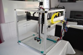
    Hi all. After a lot of work and thinking, managed to build one of these beasts.

    Building size is 50x50x35cm.
    Bed is aluminum with four kapton heaters (23x23cm) stuck underneath. Added 2 PSUs for driving those heaters.
    Hotend was E3D volcano but customer wnated the E3d Lite6 in the end.
    Electronics is ARDUINO, RAMPS and DRV8825's.
    Extruder is Bowden on RichRaps geared bowden design.

    The main problem we faced is the very long bowden tube needed (more than 100cm). Forces are high, as well as friction and this sometimes causes problems on the flow of filament. Retraction had to be 8mm to stop the nozzle from dripping when not extruding. Currently thinking to move the extruder on the X-axis, on a "short" bowden setup to get rid of the flow issues.

    Here are some photos.
     

    Attached Files:

Share This Page

  1. This site uses cookies to help personalise content, tailor your experience and to keep you logged in if you register.
    By continuing to use this site, you are consenting to our use of cookies.
    Dismiss Notice