Welcome to Our Community

Some features disabled for guests. Register Today.

My CNC Router Built Around The New C-Beam Rail

Discussion in 'CNC Mills/Routers' started by Robert Bailey, May 30, 2015.

  1. Robert Bailey

    Robert Bailey Well-Known
    Builder

    Joined:
    Mar 23, 2015
    Messages:
    117
    Likes Received:
    71
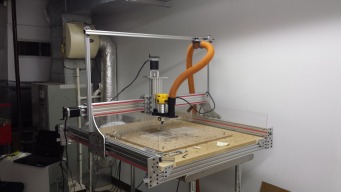
    some how I forgot to publish my build.....oops..........we did a little more work Saturday here is a few more pictures.
    I added one of the many bearings I looked at, the one on the left is what I am using the center is the same size as the store except flanged and the one
    on the right is from the store. The nice thing about the flanged bearings you don't have to do a pocket cut and if the bearing doesn't fit just do a little sanding for the clearance. the collar I got form global industrial. my build uses the one on the left. next is to wire up the switches and a jack for
    the z touch probe
     

    Attached Files:

    #121 Robert Bailey, Feb 1, 2016
    Last edited: Feb 1, 2016
    GrayUK, Peter Oakes and Mark Carew like this.
  2. Mark Carew

    Mark Carew OpenBuilds Team
    Staff Member Moderator Builder Resident Builder

    Joined:
    Jun 28, 2013
    Messages:
    2,759
    Likes Received:
    2,443
    Really great looking build @Robert Bailey
    Like the idea of the vacuum hose cart and how it can move with the spindle.
     
    #122 Mark Carew, Feb 1, 2016
    Last edited: Feb 1, 2016
  3. Robert Bailey

    Robert Bailey Well-Known
    Builder

    Joined:
    Mar 23, 2015
    Messages:
    117
    Likes Received:
    71
    thanks mark, I was just sitting there looking at how to route the hose and power to the spindle, hade some 20x20 and just started laying it out in my head and came up with it. most cnc's I have seen
    have the hoses attached to a ceiling with a spring, since mine is on wheels I think this is better... at least till something goes boom
     
  4. Mark Carew

    Mark Carew OpenBuilds Team
    Staff Member Moderator Builder Resident Builder

    Joined:
    Jun 28, 2013
    Messages:
    2,759
    Likes Received:
    2,443
    I agree, and plan to make a similar set up for my machine :) thank you for sharing.
     
  5. Robert Bailey

    Robert Bailey Well-Known
    Builder

    Joined:
    Mar 23, 2015
    Messages:
    117
    Likes Received:
    71
    worked on the vacuum dust shoe late yesterday, tested it in wood then cut out 1/2 acrylic. not sure if the screws will hold on to the rare earth magnets I epoxied onto the upper aluminum. if not I will
    try and center it up and re-pocket it for the 12mm magnets.
     

    Attached Files:

  6. Mark Carew

    Mark Carew OpenBuilds Team
    Staff Member Moderator Builder Resident Builder

    Joined:
    Jun 28, 2013
    Messages:
    2,759
    Likes Received:
    2,443
    That turned out great Robert. I have not cut acrylic that thick but it looks like you have a nice edge. I was cutting 1/4" acrylic the other day and noticed that the same settings I use for my aluminum cuts also work great for acrylic as well.
    keep up the good work bro, looking forward to seeing how this dust shoe works out with the magnets
     
  7. Robert Bailey

    Robert Bailey Well-Known
    Builder

    Joined:
    Mar 23, 2015
    Messages:
    117
    Likes Received:
    71
    I cut aluminum at .397mm , 18500 rpm at 50 ipm, the acrylic is 1mm 24500rpm an 67 ipm. I am using a single up cut spiral bit .118" dia form ebay, cost less than 2 bucks each. just ordered 10 for 12 buck from Hong Kong , still have 10 but getting spares, I cut most of my plates with just 1 bit...but these are so cheap you can toss after a couple large cuts. I broke 4 of the $30 amana bits before david helped me with the formulas.
    expensive lesson.
     
  8. Robert Bailey

    Robert Bailey Well-Known
    Builder

    Joined:
    Mar 23, 2015
    Messages:
    117
    Likes Received:
    71

    looks like it is going to hold, I tapped the holes for the low profile screws had extra 6mm ones and set them just above the surface so they would have good contact with the magnets. got the magnets at home depot, 12mm x 3mm.
     

    Attached Files:

  9. Robert Bailey

    Robert Bailey Well-Known
    Builder

    Joined:
    Mar 23, 2015
    Messages:
    117
    Likes Received:
    71
  10. Robert Bailey

    Robert Bailey Well-Known
    Builder

    Joined:
    Mar 23, 2015
    Messages:
    117
    Likes Received:
    71
  11. Robert Bailey

    Robert Bailey Well-Known
    Builder

    Joined:
    Mar 23, 2015
    Messages:
    117
    Likes Received:
    71
    check a couple posts up I posted what my speeds and feeds are for acrylic and aluminum using that bit
     
  12. UWBernie

    UWBernie New
    Builder

    Joined:
    Jan 25, 2016
    Messages:
    5
    Likes Received:
    0
    Any estimates on the overall build cost?
     
  13. Robert Bailey

    Robert Bailey Well-Known
    Builder

    Joined:
    Mar 23, 2015
    Messages:
    117
    Likes Received:
    71
    the overhaul was mostly time and the cost of the aluminum, I cut everything out of 10 x 14 inch 6061-t6 plate so maybe $60 in aluminum. my original plate were scraps from our test lab, overall it a little over $1000 for the build. I don't include tool I bought since I just add them to my collection.
     
  14. UWBernie

    UWBernie New
    Builder

    Joined:
    Jan 25, 2016
    Messages:
    5
    Likes Received:
    0
    Makes sense, have you done any accuracy and/or repeat ability testing?
     
  15. Robert Bailey

    Robert Bailey Well-Known
    Builder

    Joined:
    Mar 23, 2015
    Messages:
    117
    Likes Received:
    71
    we have done some, it has stayed within a few thousands, but you have to remember that this is a DIY hobby machine, if you are doing wood and acrylic you will never notice it, there is some backlash also.
    the only way to get a tighter machine is to build a ball screw rail system and get rid of all the wheels, belts and acme screws.
     
    GrayUK likes this.
  16. UWBernie

    UWBernie New
    Builder

    Joined:
    Jan 25, 2016
    Messages:
    5
    Likes Received:
    0
    Totally understand just want to have a reasonable expectation before I start a build that could end up looking very similar to yours.
     
  17. Robert Bailey

    Robert Bailey Well-Known
    Builder

    Joined:
    Mar 23, 2015
    Messages:
    117
    Likes Received:
    71
    did some more work this week and today, the screws in the shoe seem to hold ok. but if you put magnets on both it takes lots of effort to pry apart.

    got everything into the pelican case and the connectors on, still have the z probe and limit switches to wire up.
     

    Attached Files:

  18. Peter Oakes

    Builder

    Joined:
    Jul 12, 2015
    Messages:
    25
    Likes Received:
    19
    I love the case for you control system. Awesome :)
     
  19. Rigga11

    Rigga11 New
    Builder

    Joined:
    Apr 24, 2014
    Messages:
    9
    Likes Received:
    15
    Robert,
    I have also used a very similar design for my CNC. I am getting movement in on my Z axis in the Y axis direction. I am thinking about using your idea of adding wheels to the inside of the C-Beam. How has your machine been handling since you add those inner wheels? What is the thinness of the plates you used on your Z?

    IMG_1555[1].JPG
     

    Attached Files:

  20. Robert Bailey

    Robert Bailey Well-Known
    Builder

    Joined:
    Mar 23, 2015
    Messages:
    117
    Likes Received:
    71

    we got rid of a lot of flex with the added wheels added on the back, with yours it looks like it is really high off the spoil board and using the openbuild 1/8" plates. I started out like yours then had the machine build
    its own replacement plates. every think on mine is 1/4" 6061-t6. my next rebuild will replace the wheels with bearing guides. I am finding that there is some wiggle in the wheels, some have more than others. if
    you are doing wood projects the amount of slop most likely will not be noticed. I posted a bunch of pictures , take a close look and if you need a better look at something I can post a different view of it to help you out.
    I also posted all the sketchup files also.
    Robert
     
  21. Ronald van Arkel

    Staff Member Builder Resident Builder

    Joined:
    May 7, 2014
    Messages:
    472
    Likes Received:
    245
    Hello Robert, the latest wheels with the "OpenBuilds" marked in them are better and should have no play with the bearings, the Xtreme wheels should have even less play. Still, we are looking forward to the design with only the bearings, it will be great to see :thumbsup:.

    -Ronald
     
  22. Peter Oakes

    Builder

    Joined:
    Jul 12, 2015
    Messages:
    25
    Likes Received:
    19
    That is a really tall gantry, are you experiencing any flexing in it
     
  23. Rigga11

    Rigga11 New
    Builder

    Joined:
    Apr 24, 2014
    Messages:
    9
    Likes Received:
    15
    The Z rail is 500mm and I have a good 360mm of travel +- the size of the bit. I can not visibly see any flexing on the X (1000mm) rail and unfortunately I don't have a dial indicator to see if it is flexing. From what I can see the flex I am getting appears to being coming from where the two plates are connected between the X and Z. The plate are only 1/8in and I hope that by going up to solid 1/4in plates and adding the inside wheel like Robert has, that it will remove most of the flext I am experiencing. I plan to mainly do wood and acrylic projects. However it would be nice to have enough rigidity to be able to do some aluminum projects like making new parts to repair/build another cnc.
     
  24. Rick 2.0

    Rick 2.0 OpenBuilds Team
    Staff Member Moderator Builder Resident Builder

    Joined:
    Dec 20, 2013
    Messages:
    2,896
    Likes Received:
    1,555
    @Rigga11, If you're cutting your own plates, make them about 3" taller and move the upper set of Z-axis wheels up as far as you can. The short vertical spacing of the Z-axis wheels was an issue noted very early with the original Ox and that's why additional wheels were added higher up. The wider the spacing you can get between the upper and lower wheels, the more resistance you will have against leverage on the Z-axis rail and thus the less movement you will experience.
     
    GrayUK and Rigga11 like this.
  25. Rick 2.0

    Rick 2.0 OpenBuilds Team
    Staff Member Moderator Builder Resident Builder

    Joined:
    Dec 20, 2013
    Messages:
    2,896
    Likes Received:
    1,555
    I'm not supposed to be mentioning this just yet as its not quite public knowledge but there's a new plate that will be hitting the shop in the next couple of weeks. Its somewhat of a hybrid version that Mark has worked up based on plates originally created by Robert Bailey and Metal Guru. It solves a lot of problems on the X-Z gantry interface. It offers a wider wheel spread along the axis and is a 1/4" thick so it won't have the bending issues of the current 3mm gantry plates.

    Here's a sneak peek:
    XL plate examples.jpg
    C-Beam XLarge Plate_8.jpg RENDER_Larger Plate C-Beam Idea_Keyshot_2.177.jpg
    You'll note in the last photo it even works for side plate on a Routy style C-Beam setup.
     
    #145 Rick 2.0, Apr 21, 2016
    Last edited by a moderator: Apr 27, 2016
  26. Robert Bailey

    Robert Bailey Well-Known
    Builder

    Joined:
    Mar 23, 2015
    Messages:
    117
    Likes Received:
    71
    OH snap, this ole Tennessee Hillbilly is getting 15 min of fame ....
     
    GrayUK, Mark Carew, gwandad and 3 others like this.
  27. Rigga11

    Rigga11 New
    Builder

    Joined:
    Apr 24, 2014
    Messages:
    9
    Likes Received:
    15
    Rick thank you for sharing. That is exciting news. I'm not sure if it just me but I am unable to view the photos you posted.
     
  28. Rick 2.0

    Rick 2.0 OpenBuilds Team
    Staff Member Moderator Builder Resident Builder

    Joined:
    Dec 20, 2013
    Messages:
    2,896
    Likes Received:
    1,555
    Revised the photos. Let me know if you still can't see them.
     
  29. Mark Carew

    Mark Carew OpenBuilds Team
    Staff Member Moderator Builder Resident Builder

    Joined:
    Jun 28, 2013
    Messages:
    2,759
    Likes Received:
    2,443
    Hey guys Rick is right, we now have a really nice new C-Beam XLarge Plate, that fits on C-Beam or 80mm wide V-Slot.
    Thanks and props go out to Robert Bailey and Metal Guru for the inspiration on this one!
    Its 6mm thick and can be bolted together at 90 degrees (pre-tapped) for a super strong 12mm thick XY system.
    The screw heads are recessed so everything lines up nicely and like Rick mentions it has a nice wide wheel spread across the axis making it really stable.
    Another cool think is that you can add two standard Nut Blocks (one one each side of the plate) to add to a wider stability and more precision on the system. The slots make it adjustable to add a little preload as well. You also have the option to put an Anti-Backlash Nut Block in the center as well like we do for most of our plates.
    Well we better stop before we have to ban ourselves for spamming ;D

    We hope that you will find this plate as useful as we do and we hope to see a lot of great new Builds come from it
    C-Beam™ Gantry Plate - XLarge
    We will have the model and example builds posted as soon as we can.
    Thank you
     
    #149 Mark Carew, Apr 27, 2016
    Last edited: Apr 27, 2016
    GrayUK, Paul Stoller and Moag like this.
  30. Paul Stoller

    Paul Stoller Journeyman
    Builder

    Joined:
    Feb 28, 2016
    Messages:
    157
    Likes Received:
    107
    I may already need to upgrade my C-Beam machine even before I finish building it :) I love this. I think I may have to update my build to incorporate this in the XZ interface of my machine.
     
    Mark Carew likes this.

Share This Page

  1. This site uses cookies to help personalise content, tailor your experience and to keep you logged in if you register.
    By continuing to use this site, you are consenting to our use of cookies.
    Dismiss Notice