Welcome to Our Community

Some features disabled for guests. Register Today.

myOX : a 4' x 2' OX with potential

Discussion in 'CNC Mills/Routers' started by Serge E., Jun 19, 2014.

  1. Serge E.

    Serge E. Journeyman
    Builder

    Joined:
    May 6, 2014
    Messages:
    730
    Likes Received:
    252
    But unless your are in education and using only for personal/educational work, that costs a pretty penny or two or three ...

    In the wee hours of the morning a few voices were heard :
    • in SketchUp (at least) : if you don't create a flat surface to draw on, you are looking for trouble !
    • in SketchUcam : if generating the gcode seems to take for ever, like those lower case 'e' changing to 'E' to show progress suddenly slowing way down, you need to think about whether you are really really working off a 2D surface (see above) !
    • in life you have to KISS : Keep It Simple Stupid !
    In the first, and I had gone through the pain a few times before (sometimes age plays trick on you and lets you forget what you don't want to admit - it is my birthday today), it turns out some of those 2D drawings you are doing are not really 2D after all, especially if doing arcs and such without a reference surface.

    In the second, the little voices were reminding me of the "sometimes SketchUcam will do odd things". Turns out that if there is some minor 3D in the otherwise 2D looking design of yours (as was the case in my sign), there will be odd things going on, like that pecking action instead of following the curve smoothly and the odd dives (however minor they seem).

    As for the third, just too obvious. It just takes a birthday to get lots of kisses. :oops::duh::thumbsup:

    So I cleaned up my "2D" design, redid the SketchUcam step ... a few times (getting old and skipping steps at times). Guess what happens when you have a nice true 2D design ?The gcode generate by SketchUcam gets done in a "flash" instead of minutes and best of all this resulting gcode runs the job in less than than 40 minutes as opposed to 14 incredibly boring hours !!!

    Looking at the positive side of things :
    • DO use a simulator, it will save you material, wear and grief (not to forget the few remaining hair on your head)
    My environment is now :
    • Pen(cil) and paper - draft your thought however rough it may be (sorry, I'm old school)
    • Think hard and long about the design and what you want (hope) to achieve (that's me overthinking, but eh)
    • SketchUp Make (being free) can get you there, but it won't be as easy as you might hear or think
    • SketchUcam (also free) will get you there IF it can be described in 2D, you might have to break the design (generating gcode) into separate files to join them into one job (or not if using multiple end mills / bits)
    • MeshCAM (you start paying here) will get you there if it is 3D, even simulating 4D (multiple faces), it can separate the roughing from the finish, allow a different tool for each of the three major steps (roughing, finishing and 'pencil' clean) which you can join or run individually. Blabla ...
    • When you'll have the money and justification to spend it, you might want to start looking at some of the fancier tools ... But if you are in it for the hobby, the free or near free options are plenty good and will teach you loads through ... errors. There are tons of choices when paying. Many with specialized purposes, just like the tools in your garage - some with a think layer of dust because needed or used only once or twice, others well worn and worth every dollar paid.
    So a few pictures of the famed sign will be posted later, a short clip or two illustrating the issues from my errors and maybe a full length of the 'proper' job (under 40 minutes ?), saving you from the 14 + hours I did not get since my computer got bored before me (!) killing the run only about ... 5 hours in. Router, steppers and myOX in general thanking the computer for doing that. You can't say I'm not a patient guy, eh? Was I torturing myOX ? :nailbite: It certainly proved it can now do long runs without missing a step.

    Then ... off to a well earned (I think) birthday (celebration) dinner with the wife :thumbsup::cool:
     
  2. Serge E.

    Serge E. Journeyman
    Builder

    Joined:
    May 6, 2014
    Messages:
    730
    Likes Received:
    252
    As in 'Read The Freaking Manual" ? Sorta-kind ... I'm the type who thinks anything 'computer' should be smarter than the user and let him/her get away with just clicking. :oops: Kids can get the hang of iPads and such without having to read a manual. Why should an adult need to read manuals ? It's so ... passé, no ?
     
  3. Paruk

    Paruk Journeyman
    Builder

    Joined:
    Jul 13, 2014
    Messages:
    397
    Likes Received:
    149
    I leave that up to you to decide what is passé or not…..:)
     
    JustinTime likes this.
  4. Serge E.

    Serge E. Journeyman
    Builder

    Joined:
    May 6, 2014
    Messages:
    730
    Likes Received:
    252
    I now seem to have things back under control with myOX and the software issues.

    :oops: Mea culpa :oops: Mea culpa :oops: Mea culpa :oops:

    After a good two days of head scratching and studying my SketchUp file and all I was doing with SketchUcam, OpenSCAM doing a simulated run between what must of been nearly all the permutation possible of my errors and likely corrections, I found :
    1. for some unknown reason most of my design's outlines were floating above the reference surface. It was by only 1/64", so not obvious (for me) to see on the screen considering the final product is a sign of about 19" x 30". I think it was when I drew and copied the arcs as they were the most affected ...
    2. The worse part, some of the contour lines were actually sloped, the one which became most obvious were the long arcs on outer edge of my design ...
    3. Worse still, ya I really compounded things here, I stubbornly misunderstood the purpose min-z and max-z settings in the Machine Options under PhlatBoyz-Options (SketchUcam). Although the documentation, yes I had a quick read early on and several since, seems pretty clear, I kept using them like safe X and Y which I was doing by setting min-z to - 3/4" and miz-x to 1.5". That would 'guarantee' I would not go into my spoil board or sky high ... Ya right, eh ?
    For the first 2 issues, it took me a while to notice and then find a fix. Using a SketchUcam Phlat Edge - Phlatten selected Edge didn't seem to fix "everything". Not certain why, but it could of been me as well. Anyways, I used the extension "Flatten Vertices" - "to Z=0", highlighting everything including the reference surface. Every thing was then pushed down with no distortion since it was only 1/64". Of course, I add to erase all Phlat stuff first to be sure I didn't further mess things.

    As for the third, I must of played with the setting at some point between my first prototype sign, which did work nearly perfect, and wanting to add some elements and tweak others... I found it odd that all of a sudden, myOX would not go more than about half an inch down into the 3/4" plywood. But I could not be the cause... Not only did I have -0.5" set for min-z, but I also had something like 1.5" for max-z... The generated gcode would thus be allowed to go down ONLY 1/2" max but it could go up that 1/2" plus the 1/8" safe Z over work piece, when need to travel over it, and then drop down ONLY half an inch not the 1/8" plus 3/4" when going deep! The generated gcode would still go around the required number of times, but a bunch would just be limited to about 1/2"... the odd "mystery" deeper line segments appearing out of no where.

    Stuck in my ways, I did eventually get the purpose of these 2 parameters. It would be nice if they actually acted as 'Safe Z' rather than limit any one Z movement ... Especially when one is the negative of the other. Why could they not be just one parameter? I would not of made the error ...

    I ran the newly generated gcode over the same piece of 3/4" plywood, just in case ... I did a pretty good eye-ball alignment and the job is ran great !! The entire job took just a tad over 1 hour, compared to the 14+ hours when it was needling/pecking around the complex curve and not even going deep enough to cut through the 3/4" ...

    I will do a clean run, filming most of it. But here are a couple of pictures of the sign in its raw form and painted

    P7253391_not-painted.JPG P7253389_painted.JPG P7253390_painted-closeup.JPG

    The centre U circle is floating (initially I wanted it to be able to spin horizontally) within the fancy cutout (which would of spined as well). These inner pieces are actually held to the main portion of the sign by hidden nails - a power nailer was used with 3+" thin nails. The spinning feature is dropped for now. These two first run will be mounted on a wall anyways.

    The final sign will actually be double sided (just need to carve the lettering on the 'back" side). The spin feature might come back for that one. I would need to drill a whole into the thickness of the material to insert a 'metal' dowel to act like a spindle/bearing and keep the spacing ...

    All of this to say I was at fault for about 99% of the issues I ran into up to date with the assembly and use of this CNC router - myOX.

    Now the real fun will start as I have collected some raw material and even more project ideas over the past year, since the CNC router bug bit me last ... June was it ?
     
  5. Serge E.

    Serge E. Journeyman
    Builder

    Joined:
    May 6, 2014
    Messages:
    730
    Likes Received:
    252
    I also learned that it is better to dig a bit into the spoil board, as its name eludes do, than to finish the through cuts by hand ... even if for a paper thin layer. If I do multiple runs in a row of the same job, the waste/spoil board will mostly get worn at the same spot. Not the end of the world in itself. If I do different enough jobs in a row, the board will still be functional, although not pretty over time ... Using a 1/4" MDF, it doesn't really become a big expense either way. Especially when it can be flipped to possibly double its life.

    Also, keep the number of tabs to a minimum and don't make them too thick ... or thin. They can be a pain to clean up. For the sign I used only 4 tabs for the outer edge and each of the circles. The small cutouts had no tabs, except for the larger arrow which has two. For the first two runs (shown in earlier pictures), the tabs were nearly 1/2" wide and 30% of 3/4". I found them huge to clean up and realized, by doing the multiple runs on the same piece of raw material, a near 'onion skin' thin tab can be just as effective at holding a part. It is much either to clean out as well ...

    At one point during my issues, I forgot the spoil board, the raw material resting right onto the cross beam (v-slot). Turns out my end mill can cut aluminium with no apparent issues (3/32" pass at 120 ipm and 22k rpm). :rolleyes: Once I can get my work table parallel with the router for the entire surface, I will be able to not only cut but also pocket aluminium :duh:
     
  6. Serge E.

    Serge E. Journeyman
    Builder

    Joined:
    May 6, 2014
    Messages:
    730
    Likes Received:
    252
    Indeed. I am not at the stage of justifying the cost of some of these other tools. But this could be changing sooner than later now myOX is proving to be better then me at this CNC routing stuff. :oops:
     
    GrayUK and Joe Santarsiero like this.
  7. Serge E.

    Serge E. Journeyman
    Builder

    Joined:
    May 6, 2014
    Messages:
    730
    Likes Received:
    252
    A big thanks to Swarfer, over at PhlatForum for the helping hand and some insight on SketchUp, its behaviour and how SketchUcam puts up with it all.

    Turns out SketchUp lists entities in "no particular order". For a (short) while I thought it was bringing the last edited entity to the top of a list of entities and then SketchUcam did its best to optimize the rapids (air time), which it tries. But then things would seem to be randomly ordered no matter what. Even when I did the SketchUcam stuff over from scratch in a very specific order ... I would end up with a different sequence of gcode. Changing the tiniest thing in SketchUp would do ...odd things to the order SketchUcam generated the gcode. It really through me for a loop ... It is just a SketchUp behaviour. Live with it or change software.

    I suddenly remember a few others mentioning there is usually no need to tell SketchUp to draw circles with too many line segments ... It will just slow it down and extensions (ie SketchUcam) will know it is a circle or an arc and handle it accordingly anyways. Sure, the SketchUp file will look real pretty and all on the screen, but that's about as far as it goes when drawing too precisely with SketchUp.

    So I learned a few more things with this first 'real' project of mine and Swarfer's explanations :

    • first, when doing raster to vector conversion a simplification process is a must since the conversion will likely create thousands of line segments/entities. Many of these won't make any difference. At best, it will slow things down and, at worse, it will mess things up! This means using extensions: EdgeTools2 (ThomThom) to basically get rid of the excess details, RepairBL&Phlatten (SketchUcam) to further join neighbouring segments which are just about perfectly aligned and Weld (TIG) to make curves out of neighbouring segments (mostly so you don't have to click the individual segments to select the curve). As Swarfer has shown me, this gets rid of lots of segments without loosing details once milled/routed and it makes your job on screen easier ... Call it near lossless optimization.
    • second, don't be afraid to split the design into simpler parts sharing a reference point. This will also make SketchUcam's work as well as yours that much easier. The individually generated gcode can be joined with Gcode Joiner (SketchUcam) or you can run them individually, giving your machine a break between each... This could also allow you to change tool, do roughing then detailing, go for a donut and coffee without worrying about your limit switches failing or the cat jumping on your machine with an end mill spinning at 20+k rpm, etc. It is good old "divide and conquer" with a touch of "keep it simple ..."
    • third, apply some martial arts : use your opponent's weaknesses to your advantage. Just as many suggest to work on a bigger than life version of a design to get more details/precision within SketchUp, you can also scale the design down and SketchUp will join smallest entities into some it can handle (> 0.001"). Thanks Swarfer for the enlightment, it should of been evident...
    • fourth, group things for SketchUcam. You can then control the order the gcode is generated. Groups are done first within the SketchUcam processing. If everything is in one or more groups, you have full control of the order these groups are processed. Otherwise, SketchUp's ADHD will sorta-kinda randomize things on you with no apparent logic nor reason. It just does it.
    I am now ready to tackle my next sign. This time its for my mother-in-law (teaches special education) ... So it better be good, eh ?
     
  8. Serge E.

    Serge E. Journeyman
    Builder

    Joined:
    May 6, 2014
    Messages:
    730
    Likes Received:
    252
    Oh, wait. Here is the full length, unedited, uncut, ... movie of myOX cutting the UncoverU sign. So get some popcorn, your comfiest pillow and be ready to watch a long, very long, boring YouTube ! You might want to turn the volume down a tad ...


    Feel free to jump around the movie. I won't be offended in anyway ... You can even replay the exciting parts if you wish.

    Not to spoil the ending for you, my camera ran out of battery at the end of cutting the front of the sign. So you wont get to see the exciting board flipping, realignment of the material (surprisingly fast and easy) and cutting the lettering into what is the backside.

    Here are a few photos as well :
     

    Attached Files:

    Paruk and GrayUK like this.
  9. Serge E.

    Serge E. Journeyman
    Builder

    Joined:
    May 6, 2014
    Messages:
    730
    Likes Received:
    252
    Are you ever in luck !

    I did film the carving of the backside afterall. So here it is ... quite short compared to the front side, but just as exciting to watch.


    It is my very first complete true sign with a purpose in life. So I had to show you the movies and pics. Sorry if it bored some ...
     
  10. Tweakie

    Tweakie OpenBuilds Team
    Moderator

    Joined:
    Jan 18, 2014
    Messages:
    784
    Likes Received:
    326
    Excellent work. :thumbsup:

    Tweakie.
     
  11. Serge E.

    Serge E. Journeyman
    Builder

    Joined:
    May 6, 2014
    Messages:
    730
    Likes Received:
    252
    Thanks ... now I'm looking for some ideas to carve/cut out of just about anything I can get my hands on and myOX can handle.

    I also received an 'extra long' 1/8" end mill ... actually just 3" or so with a 1" cutting length and my father-in-law just gave me a few 'scraps' of thick oak and other bits from old furniture. I'm also driving by piles of clean looking skids ... a good source of free wood many seem to do miracles with that kind of stuff.

    I better get a few :sleepy: as tomorrow, only a few hours away now, is an other day. I have to build a stand for the UncoverU 2-sided sign my wife painted and varnished. Teamwork, yes ! :thumbsup: Oddly enough, she felt she had the toughest part of the job ... I just looked at a router moving around for an hour or so all by itself. :confused:
     
  12. GrayUK

    GrayUK Openbuilds Team Elder
    Staff Member Moderator Builder

    Joined:
    May 5, 2014
    Messages:
    1,668
    Likes Received:
    627
    Excellent Job!!! :thumbsup::thumbsup:
    At least it was shorter than some of your threads! :D
    Really good to see it doing its thing. I bet you are pleased at long last.
    Well done my friend. :thumbsup:

    Gray
     
  13. Serge E.

    Serge E. Journeyman
    Builder

    Joined:
    May 6, 2014
    Messages:
    730
    Likes Received:
    252
    :ROFL::ROFL::ROFL::ROFL::ROFL::ROFL::ROFL::ROFL::ROFL: I think I just pulled a muscle laughing so hard. Good one ! :thumbsup:

    I'm like a kid in a candy store. I just don't know which candy to go for at this stage :rolleyes:
     
    GrayUK likes this.
  14. Serge E.

    Serge E. Journeyman
    Builder

    Joined:
    May 6, 2014
    Messages:
    730
    Likes Received:
    252
    I just could not wait any longer, so I tried my hand ... or should I say myOX ... doing my very first (ever) inlay project using what I had lying around. I have gathered lots of different material/stuff with many projects in mind since getting pulled into the DIY CNC thing nearly a year ago now.

    I grabbed some scrap 3/4" plywood from the three signs. I looked for an outline/shadow image of something interesting (like that Frog Table seen on YouTube). Vectorized the outline through one of the online free raster to vector tools. Tweaked the resulting vector as I was shown/explained by Swarfer to simplify the paths for myOX, making certain the 1/8" end mill would clear all curves and lines. Then ... well, things got interesting between SketchUp's behaviour & SketchUcam's workarounds and ... features, not forgetting my current skill level (or lack thereof).

    First, SketchUp does not handle offsetting of curvy or close proximity lines. It tends to make a mess. A reason SketchUcam, as when doing a pocket, breaks things up unable to cover the entire area for a nice clean pocket ? The trick here is to trace temporary lines to give SUC a chance to do a good job. SketchUp still in the picture, it does not always work especially if there are lots of curves and/or sharp angles. In wanting the pocket to create a particular pattern (do not ask me why, it's just an OCD thing I guess), I manually did the offsets - cleaning up SketchUp's mess along the way. A few hours later, I had what I wanted, or just about. SketchUcam could then follow those offsets and a pocket would result ... During the clean up, lots of tiny little line fragments had to be hunted down. Blabla ...

    Second, what was I going to use to fill the pocket ? Well, through accidental experimental discoveries over the last few days I did find out myOX could very easily cut aluminum at a good pace too. Yes, I (!) forgot to use the sacrificial spoil board at some point and myOX happily cut into some of the V-slot just as easily as it did : MDF and plywood. It was just as impressive as it was unexpected. The size of my router certainly helping. Blabla ...

    Unfortunately, that's all the aluminum I have on hand (for now). I was planning on using thin styrene lighting panel, the "cracked ice clear" finish. It should give a nice finish, light bouncing off at various angles and all that glittering effect ... I just needed to do the pocket .05" deep or so given since the styrene panels are not perfectly finished. There's a little unexpected twist of using SketchUcam, at least for me at this stage : you can't tell it how deep to pocket in inches. It's done in % of the material thickness... Great for most work, not so great if you want precise depth no matter how thich the material used ...

    That's when the third little situation reared its ugly face once again : my gantry and table surface are not quite parallel. Oddly enough it's not the gantry sagging in the middle under the weight of that hefty router of mine, it's the table top itself sagging in the middle ! I did had a single screw/bold down the middle of the double v-slot X axis to keep both of them inline - the front was sagging a tad. Rather than digging into the table, myOX floats above it ... go figure ! Only I could pull that off, eh ? So I have to fix my table frame somehow. That will be yet an other story / phase ... blabla ...

    Anyways, here is the result (not quite finished) of my very first inlay attempt :

    IMAG0537.jpg

    Notice the 'shiny' gecko cutout in the background ? Nice, eh ? I figured I would spray paint the styrene cutout, on the 'crackled' side to do a mirror like finish on all those angled faces.

    Well, the fourth issue showed up : I cut the gecko on the wrong face of the styrene sheet ! So all that shiny multi faced mirror like finish ends up facing the wood. Doh ! Wait ... if it's like a mirror, it be shiny on the other side, things tend to work themselves out, right ? Guess again, the opposite side is grey as can be :

    IMAG0538.jpg

    Now for the fifth issue : man that is a tight fit !! I had to use a much thicker piece of lexan and... along with the gentle touch of a hammer, I got the cutout to fit in the pocket without cracking the crackled styrene. I can also remove it with little pain and, most important, no shattering. Man, a better fit and I would be an expert. It's all in myOX doing the precision work rather than me.

    So now I have to finish the wood - the wife wants to paint it black (like some of the other furniture we have), I reinsert of the cutout and maybe use liquid glass epoxy stuff to finish the "Gecko table top" ... I

    t is about 19.5" round. That is just shy of the maximum Y axis myOX has.

    For the next attempt, I want to do a larger table top ... doing the pocket in 2 or maybe 3 shots ! myOX is wide enough to take 50+" (X axis), but I can only do just shy of 20" for length (Y axis). However, I need to fix the 2 mm dip in the work surface of myOX ... Pocketing does not like the dip ! I'm also really tempted to extend my Y axis. Change the existing 750 mm length to at least 1000 mm, if not the full 1500 mm. Then I would have a reason to rebuild myOX's table/stand ...

    Did I loose anyone in this lengthy post ? Sorry ...
     
    Knut Bøje and Joe Santarsiero like this.
  15. Allan Luomala

    Builder

    Joined:
    Sep 10, 2015
    Messages:
    2
    Likes Received:
    0
    Hi Serge. I discovered this thread whilst searching for the manual for the Craftsman router that you are using. I built a ShapeOko2 machine, and have been using a Dewalt DW660 trim router, but was thinking about upgrading to something beefier.

    Anyway, I was trying to find the diameter of the router, hoping that it would fit into the Dewalt 611 spindle mount that Inventables sells (link). If you would be so kind as to give it a quick measure, it would be greatly appreciated.

    Great work, BTW, on documenting your successes (and failures, which I learn from).

    Allan
     
  16. Serge E.

    Serge E. Journeyman
    Builder

    Joined:
    May 6, 2014
    Messages:
    730
    Likes Received:
    252
    I used a mount from Chris (Laidlaw) for a perfect fit. If it was "custom", he should still have the diameter for the router I have. Not certain about the DW660 diameter, would need to look it up... The 611 is quite smaller. A few others here can also supply you with mount, plates, etc. Robert (Hummel) comes to mind on Canadian side.

    By the way, I use a Mastercraft (Canadian Tire) not Craftsman (Sears) - I always get confused between the two ... They most likely come from the same mold, changing the colour of the plastic and sticking different label on them. [!! tangent alert !!] Have you ever wondered how competitors end up with almost identical products ? Is it 'perfect design' so it can't be any different to be good; a lack of any imagination; ...or just plain secretely sharing stuff (thus working together at some level) ? [back to regular schedule ...]

    I figured I would have a lot more to say, of value, about my failures than successes :oops: Like you point out, we (at least I) should learn more from others' mistakes rather then venturing off a step by step guide (the "success")... It lets me try things w/out making the mistakes already made by others ... Afterall, making (calculated) mistakes is how we learn from the day we are born.
     
  17. Allan Luomala

    Builder

    Joined:
    Sep 10, 2015
    Messages:
    2
    Likes Received:
    0
    Thanks for the quick reply, Serge. I think I am going to go a different rout(er) :p. Some fellas on the ShapeOko forum I frequent mentioned that it is likely too heavy for a stock ShapeOko2 (or even the newer SO3), and the sale is over (I always forget that CT sales end on Thursdays!).

    I am going to investigate brushless spindles, and see what I can get for a modest investment.

    Good luck on your journey!
     
  18. Serge E.

    Serge E. Journeyman
    Builder

    Joined:
    May 6, 2014
    Messages:
    730
    Likes Received:
    252
    Just moving (continuing) a conversation I started over at an other build on the subject of getting my table top flat (more than level as it is all relative). I felt like I was taking over the build and distracting its followers.

    So here is a summary of the conversation to date.

    For a large OX build, it is probably best to use a tension box approach to make as flat a table top as possible. It does take tad more preparation work (and tools) than I would want or can have at this time. The concept is simple and would work ... The suggestion was received of adding a metal top plate. This would allow for use of magnetic hold downs. So it may become the route I will take at some point down the road.

    My short cut to getting my table top flat seems to introduce some heavy corner length to force the cheap 2x4 and OSD into a flat stable surface. But that seems like a lot of work for a half bake solution ...

    A while back, in other forums, I also saw the use of self-leveling cement and such. But I since found out these are not that self leveling. They also need a firm/stable base with no flex ... or it could crack. Back to square one ... or the tension box idea.

    Suggestion received also included tweaking my existing sagging table top to make it appear flat - dowels and such to keep the work piece level/flat relative to the tool end. I have about a 2mm sag towards the centre of the table. No apparent flex on the myOX's 1500mm X axis even with the heavy router being used. I have a screw holding the two length of V-slot together near centre of length. Unless there is a downward flex and my table top has more than a 2mm sag !

    Sort of went off talking about a vertical configuration, up against a wall, for any large OX as it could possibly help resolve the flatness issue but mostly the need for less floor space. An issue as I also want to increase my Y from 750mm to at least 1000. Turns out the 750 mm only gives about 20" of working length (Y) when I could really use at least 24". This translate to more floor space and having to either extend or redo my table ... or at least the top. I still would want to allow for extra depth - the top removed at least within a section (work on 6+" blocks, even if just the usual 2-3" deep per face not to introduce Z issues).

    Then there is the issue of hold downs for the work piece. Some appear to find the use of two sided tape as being overlooked - seems to work for many. How strong can it hold the work piece AND then be easy to remove ? Vacuum tables are great, but what if there are many cutouts ? What about the dust/chips being sucked in ? It would need filtering and such ... also needs vacuum, etc. So that suggestion of a metal top becomes attractive with magnetic hold downs.

    But I also found some neat (expensive) bench dogs advertised over at Rocklers. Just need strategically placed holes to hold those bench dogs while their adjustable clamps hold the work piece in place. Makes for easy and rapid hold downs... That tension box idea is circling back just need to have blocks in the right places within the box to serve as bench dogs' holes. It would also work on a (near) vertical configuration.

    But then I would need to change the Y (or X) axis to rack and pinion (or precision lead screw of 1500mm or so !) for axis in 'climb' mode. Maybe just have counterweights so the GT3 belt still think they are moving the mass and not carrying it up / down the wall ...

    And that still doesn't address the issue of a flat table surface !

    Which brings me to : what about using a tough as nail exposy ? It will self level. It will be flat, if properly applied. It can become a surface to apply a metal sheet, the MDF waster board or whatever so it is not directly exposed to the tool end ...

    Here is what I just found on the latter. They created a very large (8' x 17' !) control surface using epoxy :

    http://www.precisionepoxy.com/TableTopSurfacePlate.htm

    As anyone tried this approach for a flat work surface for their CNC ? I suspect someone will point out they probaby have tension box under that large control surface to keep it solid and nearly flat to start with ..
     
  19. Serge E.

    Serge E. Journeyman
    Builder

    Joined:
    May 6, 2014
    Messages:
    730
    Likes Received:
    252
    Now here is something which might become the base for a pseudo vertical OX. They made a router module for a panel saw (go to 6 minute mark) :


    Just wondering if it would be best to try and shift the work piece back and forth - potentially taking a lot of room but a 'simpler' design, or if the entire ... X/Z gantry should be shuttled back and forth over the work piece.
     
    #349 Serge E., Dec 14, 2015
    Last edited: Dec 14, 2015
    Mark Carew likes this.
  20. Serge E.

    Serge E. Journeyman
    Builder

    Joined:
    May 6, 2014
    Messages:
    730
    Likes Received:
    252
    Wait, here is something which might just be a good base to start building a vertical OX on the cheap :


    Paul Stone over at A2 Equipment might be onto something with his kit to build panel combo saws. He offers the plans for free, as far as I can tell thus far. He also sells the key parts (none of the wood or tools) for less than 350 $us as a kit, compared to the 1000+$us of the system previously mentioned.

    Just have to figure out how to move things around wih CNC and you get one big OX taking a lot less room in your garage.

    Of course, if this big OX needs to do detailed work, it might take a while to carve out a 4'x8' (or bigger)
     
    Mark Carew likes this.
  21. John Meikrantz

    John Meikrantz Well-Known
    Builder

    Joined:
    Nov 2, 2014
    Messages:
    169
    Likes Received:
    56
    Reminds me of the Crawlbot from Printrbot, only horizontally. Cool idea for maximizing footprint and minimizing space.
    Crawlbot | Printrbot

    -- John
     
  22. Serge E.

    Serge E. Journeyman
    Builder

    Joined:
    May 6, 2014
    Messages:
    730
    Likes Received:
    252
    There is so much information here at OB ... call it a refresh. ;)
     
    Mark Carew likes this.
  23. Serge E.

    Serge E. Journeyman
    Builder

    Joined:
    May 6, 2014
    Messages:
    730
    Likes Received:
    252
    To get the conversation back to myOX, I have worked on and off with it for the last little while trying to work out a few 'bugs' ...

    The table is as important as the rest of the machine !

    Turns out my table, given its width and the material used, was sagging in the middle by at least 2 mm near the center. Not ready to build myself a new table, I did the next best thing: added a couple of bracing 'legs' at center to span the table top & bottom frames... working great. Wood being wood, especail 2x lumber, it is bound to move as the temperature and humidity changes in the garage.

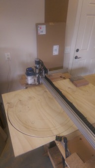
    Once the table issue solved, or at least addressed, I redid my spoil board. I was trying to do the entire surface, not just the work area. The problem with this approach is how the heck to you plane the surface beyond the reach of the tool end of your machine without a side effect when working very large pieces of material ? So I did a spoil board no bigger than the work area. Doh ! Got a 2" wide bit and made the surface "parallel" to my gantry. Also through in a 6" x 6" grid, including dog holes ...

    Guides, jigs and other details

    So I have a nice flat work surface, but how the heck do you hold the large ... and small work pieces ?

    Let the dogs out ! IMAG1064.jpg No, not that kind of dog.

    At first, I figured I needed guides to hold 2'x4' pieces to cut and mill stuff out of. Sounds easy enough ... So I designed a left and a right pair of guides. Oh no ! I needed the dog holes to be out of reach of myOX working end ... So I used the 6"x6" grid it had engraved as a guide to extend lines to hand drill the 3/4" holes. Oops, I don't have a photo ... you'll get a peek later on.

    Then came the two guides to align and hold the 2'x4' work pieces. It could be plywood, acrylic sheets (ya, those ceiling thingies I used to cut out the gecko form to inlay in a table), etc.

    IMAG0857.jpg IMAG0860.jpg IMAG0861.jpg IMAG0862.jpg

    My hand drilled dog holes are, unfortunately, not quite parallel to my Y ... However, with the guides, I could have a 2'x4' peg board (all I had on hand) as a spacer sacrificial board and then the 2'x4' work piece needing engraving and engraving. The 2'x4' was bit crooked, 3 mm or so over the 24". No big deal as whatever I cut could care less as long as I had a margin, which we, or at least I, always have.

    Initially, the idea of the guides was so I could flip the work piece and keep it perfectly aligned to work on the back face. Well, the 3 mm does come in play here. In addition, those precut 2'x4' are not quite to spec. Adding couple of wedges and, tada, the work piece doesn't move. At 3/4" thick, it stays nice and flat as well. When flipping, if parallel to my Y, I just needed to remember to butt front to bottom corner and then back to top corner ... fingers crossed !

    All this came about when I needed to cut a croquignole game board. The official diameter is 26" for the play area plus another 2", thus 30" diameter with gutter area... still not counting a finished decorative edge. MyOX can only cut 20" (really almost 20.5") in one axis, so I designed the game board in sections no bigger than 20" in one dimension, the other could handle 50+". The back of the game was to be a Chinese checkers or other board game. This was the need to precisely flip my work piece.

    Having drilled the outer dog holes by hand, it was too late to do anything about it ... unless I redid the board ... I could cheat the guides to bring things back in line, but that would be tricky (for me, given I messed up the drilling in the first place !) I made those guides so it made about a 2" top and bottom (safe) edge, just in case I needed clampling. Turns out to be a waste as I could of used this 4" for other guides, jigs and whatnots.

    My other issue was having broken down the game board into five pieces : center plus four corners, I had to figure a way to glue them in one solid level game board. For me, that would of been a challenge I was not looking forward too. I did cut one almost complete kit out of a 2'x4'. Just to see ... I would of needed an other 2'X4' to get the 5th segment done. I was not looking forward to assembling these 5 pieces.

    There had to be an easier way ... but I could I cut a 30+" diameter game board when myOX could only do 20" in one axis ? The other easily does 52".

    Work in sections, get more dog holes and a better guide !

    I could get 3 pieces of about 32"x 48" out of a 4'x8'. If you remember, long ago I mentioned myOX wanted to cut at least 48" wide (X) over as long as needed. It just needs to work in 20" sections (Y), sliding the work piece through one section at a time.

    Time to have myOX drill more dog holes over its 6"x6" grid. That's 24 to be perfectly aligned. No sweat for myOX, took less time than drawing the layout in SketchUp/SketchUcam. the 3/4" holes are dead on, in diameter and position.

    I now needed a guide which could square the work piece and allow it to slide as myOX needed to work on the next section. I modified the design of the earlier guides. This time, I just needed to take car of the left side, allowing the work piece to be as wide as it needed to be, without going over 52" or so.

    IMAG1069.jpg IMAG1076.jpg IMAG1074.jpg

    The first photo above shows the 'corner' guide with it's zero being at myOX's zero. No margin was built in this time. Whatever I cut or engrave would have to have the safety margin, not to cut into the guide. Being MDF, I could always cut new ones in minutes at worse. The second photo shows this first guide while the 'slider' is in place and shows in the third.

    Now I was ready to cut well beyond 20" in Y. I just needed to incorporate an alignement marker at each sections of the design. Here's the croquignole game board as one piece along with the sections to work with SketchUcam to generate the G-code :

    Croquignole-SU-layout.png

    I'll do a resource to explain this along with the work flow and how myOX surpassed my expectations - making the process much easier than I thought. Sure, it took me and my lonesome brain cell a few days to work things out in the vast open space of my head. However, here is the first result :

    IMAG1071.jpg IMAG1074.jpg IMAG1077.jpg

    Now I need to add some colour and finishing ... then melt/mold some HDPE for the game pieces.

    It's all coming together, at last, with myOX.
     

    Attached Files:

    Mark Carew likes this.
  24. Serge E.

    Serge E. Journeyman
    Builder

    Joined:
    May 6, 2014
    Messages:
    730
    Likes Received:
    252
    Here is part 1 of 2 of the video. The 2nd part should be all uploaded in about 2 hours (slow DSL uplink, sorry).


    This is the routing of the first 'half' of the Croquignole game board as once piece out of a 28" by way too long (but not long enough for myOX or garage) 3/4" plywood. If you can stand going through the full 20 minutes or so, you will notice a few things I can't explained (and a few I might be able to explain). In no particular order, just to make things more existing :
    • as it pockets the center 'hole' of the game board, notice how deep the first pass is (!) That's not me asking for this, the generated G code out of SketchUcam did that. You can also see this as it routes the numbers BUT not the lines. In the center hole, the next few passes are at the right depth of cut. I will admit I did and undid the SketchUcam part several times. Maybe SketchUP gets a tad confused and doesn't really erase the SketchUcam traces as it should. Maybe it's the opposite. I don't know. I do know I can cut deeper than 1/8" with the 1/8" bits. Cool ... maybe not ?
    • Look as it does the inner portion of the "1" of the third "15" (near 'center' of board). What the heck ?! The generated G-code does that segment about 11 times (!!) in a row. I certainly didn't ask for that. At least not knowingly. Weirdest thing is that it was also doing this on a few of the "1"s until I decided to remove the respective traces. Then I noticed the 'surface' was pure white BUT not reversed (I don't know what it was). So I removed that surfaced, drew a line connecting opposite sites of the "1" to get a "normal" surface and removed the line. Then I redid the offsets to get the lines to route along 12.5% deep. All but this third "15" became ok at that stage.
    • I am always fighting SketchUP and SketchUcam : the 'box' around the "10" area should of been a single trace. Not so, I had to do some weird division to avoid the 'needling' effect - when the G-code traces the line backwards but cuts tiny segments forwards (!) Turns out I had to do the half circle with the two straight segments as one element, then the inner half circle and the dividing line to get rid of the "needing". Other segments/elements needed the tiniest line to be added at extremities to get rid of the needling... Go figure, eh ? I am certainly doing something wrong. But I'll be a monkey's uncle if I can figure what it ...
    • the 'chips' are packing rather than being ejected. That's probably my 'speeds and feeds' at work. Router is at 20k rpm with feed at 50 ipm. The bit is a ... 2 (?) flute 1/8". Maybe I should spring for G-Wizard, eh ? The cuts are quite nice, no sanding needed. But final work needs a good blow and some brushing to remove the packed 'chips'. It can't be good for the bit life to cut through this... But, heck, these are China specials at less than a buck a piece and they keep going and going ...
    • let's see, there was a few other things I had noticed ... I'll let some of you point them out to me.
    A few more pictures will follow as well.

    Second half of the board will be shared as soon as my DSL finishes the upload. It takes hours to upload them. So am I will be bounding two DSL circuits to help until FTTH (fiber to the home) or FTTN (fiber to the node) comes around in my neighbourhood. Should be an other year or so from what the ISPs are telling me. Maybe cable will show up before then ... not holding my breath though.
     
  25. Serge E.

    Serge E. Journeyman
    Builder

    Joined:
    May 6, 2014
    Messages:
    730
    Likes Received:
    252
    Here's the second part.

    The board slides down about 13", the table and previous job marks aligned before starting routing the rest of the Croquignole game board.


    Tada ... one solid 26" circle out of a 20"x52" workarea on myOX. Easy-peasy as some would say.

    Now if only I could figure out what I am doing wrong with SketchUcam I could produce more board games. I'll probe David for some aspects I can't seem to get working right. I know he has a solution.
     
    GrayUK likes this.
  26. Serge E.

    Serge E. Journeyman
    Builder

    Joined:
    May 6, 2014
    Messages:
    730
    Likes Received:
    252
    Did a test sign of 3.5" x 15.75" with just my name using SketchUP and SketchUcam to check on something - my depth of cut is still off. SketchUcam gets a bit thrown off with some curves/lines, doing some 'backtacking' or 'needling' ...

    Turns out it's my clamplng, or lack there of. For this small sign, I had the work piece snug against my corner reference at zero (bottom left corner) and a single clamp at the bottom right corner. And there was my issue. The left end of the work piece was rising up enough to mess things with depth of cut at then end of the sign. Not much mind you, at least not for a sign. But tons if this was for an inlay ...

    So I need to figure a good way to clamp my work pieces, especially the smaller stuff ... The approach taken by ... shoot ... I forget and I can't find the post at this time ... Anyways, its a "float" pressing down on the work piece as the router moves around. This forces work piece down and should solve (most of) my problem. I just have to find the post to adapt to myOX ...

    In talking with David, of SketchUcam fame, I also have to pay more attention to my editing a SketchUP file during setting up tracing w/ SketchUcam. SketchUP reorders the line/curve segments as one edits, possibly flipping start and stop points, etc. This reordering then affects SketchUcam, especially the G-code generator. The more complex the curves are, the more the effect can be important. David is tons of help and I will try a few of his 'tricks' to keep the effects at bay. I also have to be more methodical when 'sketching' my jobs ...
     
  27. GrayUK

    GrayUK Openbuilds Team Elder
    Staff Member Moderator Builder

    Joined:
    May 5, 2014
    Messages:
    1,668
    Likes Received:
    627
    You should know better by now Serge. :D
    I know the posting you mean, but I can't remember either.
    I know Mark commented on it, so a search through his recent posts might help. :thumbsup:
     
  28. Serge E.

    Serge E. Journeyman
    Builder

    Joined:
    May 6, 2014
    Messages:
    730
    Likes Received:
    252
    I should know better for certain. :oops: Maybe I should work on that "Do's and Don'ts" and be the first to read it ... ;)

    Mark has a lot of posts, but I'll find it and work on something similar for myOX... along with a setup for the vacuum before the wife gets too upset about the dust working its way inside the house. It looks like I'll be running myOX much more often, along with little brother C-Beam which should soon see daylight and a few other toys I have in mind as people ask me for all sorts of stuff.

    The fun should be starting real soon now. :)
     
  29. Serge E.

    Serge E. Journeyman
    Builder

    Joined:
    May 6, 2014
    Messages:
    730
    Likes Received:
    252
    Doh ! I made a comment (or two) on it. Just found it. It's a recent build by Florian Bauereisen :

    Dust Boot and Holddown in one | OpenBuilds
     
  30. Florian Bauereisen

    Florian Bauereisen Well-Known
    Builder

    Joined:
    Feb 24, 2014
    Messages:
    188
    Likes Received:
    60
    Hi,
    since you mentioned my build:
    It does work great ... if used for what it is intendet for.
    It is designed for holding down thin material like up to 3mm modeller ply or 4mm poplar and balsa or plastics of course.
    I do model areoplane kits with it to get you a feel for its intention..
    It is not a hold down for say heavy birch planks or for sort of 3d surfacing/sign making...
    Reason for that: you cannot press down too hard before the hold down will generate sort of a slip n stick by it self and aditionally it might ruin your surface. Also you should be using a levelded spoilboard for it. There is just a few mm which the hold down can travell... using longer screws and springs will not solve that as it will loose its stability and the slip n stick will devellop even faster..

    greets

    flo
     

Share This Page

  1. This site uses cookies to help personalise content, tailor your experience and to keep you logged in if you register.
    By continuing to use this site, you are consenting to our use of cookies.
    Dismiss Notice