Welcome to Our Community

Some features disabled for guests. Register Today.

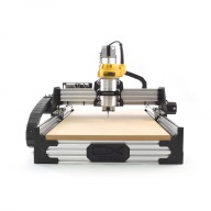
ooznest OX CNC Machine

Discussion in 'CNC Mills/Routers' started by Ryan Lock, Apr 28, 2015.

  1. Ryan Lock

    Ryan Lock Veteran
    Builder

    Joined:
    Oct 12, 2014
    Messages:
    530
    Likes Received:
    294
    Yup, no reason why you couldn't do this, it is not hard to extend at all really.
     
    Stigma likes this.
  2. Stigma

    Stigma New
    Builder

    Joined:
    Sep 30, 2015
    Messages:
    7
    Likes Received:
    1
    just ordered a 1000x750 kit and see how it goes... :thumbsup:
     
    Ryan Lock likes this.
  3. Ryan Lock

    Ryan Lock Veteran
    Builder

    Joined:
    Oct 12, 2014
    Messages:
    530
    Likes Received:
    294
    Thanks, order received! we will get is shipped asap.
     
    Stigma likes this.
  4. cruz1445

    cruz1445 New
    Builder

    Joined:
    Mar 25, 2015
    Messages:
    23
    Likes Received:
    6
    My ooznest ox is still running strong everyday. You wont regret their kit.
     
    Ryan Lock likes this.
  5. Stigma

    Stigma New
    Builder

    Joined:
    Sep 30, 2015
    Messages:
    7
    Likes Received:
    1
    Any suggestion regarding the controller board ?

    Already have some stepper drivers (with TB6600).
    Analogue voltage 0-10v to control the spindle
    Home/limit switches.
    Start/stop dust collection system.
    Connections to build an external panel.
     
  6. Ryan Lock

    Ryan Lock Veteran
    Builder

    Joined:
    Oct 12, 2014
    Messages:
    530
    Likes Received:
    294
    Great to hear!

    I would usually recommend the cnc xpro, but as you already have drivers that won't be an option. One suggestion would be a pibot controller.
     
  7. davestrength

    Builder

    Joined:
    May 29, 2015
    Messages:
    18
    Likes Received:
    19
    I'm just getting my Ooznest OX build running. It's a 1000mmx1500mm version. This is my first CNC machine, and the Ooznest kit is perfect for that. I've got a background in electronics and industrial automation...but my mechanical skills are not as polished. So, the Ooznest kit, and instructions were exactly what I needed. I can't say enough of how clear, thorough, and complete the kit is. Great job on that Ryan!

    Having the kit parts so thoroughly organized and labeled was such a luxury. The kit went together flawlessly, and was very enjoyable to build. IMG_6770.JPG

    After mechanical assembly was done and I took measurements of the final machine size, I built up a wooden table made with breakdown bed-bolts so it can be moved. Where the machine sits, only the frame was built...that is there's no table top under the machine. This is so I can mount stock vertically since I plan to machine parts for woodworking. IMG_7003.JPG
    IMG_7019.JPG
    For the controls, I went with Mach3 software (my brother gave me his copy he no longer uses), Gecko G540 driver, and the Warp 9 Ethernet Smootstepper (ESS.) The ESS allows me to run everything on a crappy old dual core laptop running Windows 7. There's no missed steps or data underuns (well as long as you disable the screen saver and low power modes!)

    I built up a control cabinet using a leftover enclosure, parts, relays, switches, terminal blocks, etc., I had on hand. Unfortunately, my box is a bit too small and everything is quite tight inside. I really needed a box twice the size, with Panduit to hold the wiring. IMG_7082.JPG
    IMG_7124.JPG IMG_7128.JPG
    I had a 20amp Meanwell 24volt PSU on hand and used that as a PSU. I'm in the US, so the entire machine runs off a single 220v feed (since the VFD requires 220v). One leg of that provides my main 110v power, and a switch on the front turns on the master control relay (MCR) and 24v supply /control power. A contactor tied to the MCR switches on the 220V source to the VFD. Lights indicate that 220v is present (red), 24v MCR is on (green), and VFD is enabled (yellow). I have a relay for enabling the VFD...but also use a separate input for the Estop circuit. IMG_7283.JPG

    Strangely, the way the Gecko G540 is setup...the EStop is not wired to drop out the MCR as you would normally do in a control scheme. Rather, it's treated more like a safety system input...where Estop is just another input and the controller is responsible for dropping power. I didn't like this at first...but it turns out it provides some benefits (like maintaining torque and position on the motors while Mach3 goes into software Estop....handy for tool changes!) But the G540 responds correctly to the hardwire estop button and drops all power to the motors.

    A single hardware Estop button is on the front panel of the cabinet, and two limit switches are present on each axis (8 in total.) I initially only planned on a single set for the Y axis...but later learned that Mach3 can use a separate set for each motor on the Y axis when homing. That is, with switches on each side, it will ensure both switches are made during homing in order to reset any racking that has occurred due to missed steps, manual tampering, etc.

    I used microlimit switches, but really need a better way of terminating the wire. I soldered them, but that left the 24v connections unprotected. I threw some electrical tape on them for the time being...but I really need some decent plugs or termination solution. Still looking for that. IMG_7286.JPG

    I bought some e-chain / drag chain off Amazon for the wire management. That works surprisingly well. For wiring the limit switches I've temporarily ran the wires under the machine. Next time I disassemble the machine..I'm going to drill wire holes in the corner endplates so that the wiring for the Y axis switches can be run through the inside of the V-rail. I do this for the x-axis switches and it works great; so clean.
    IMG_7292.JPG

    I got a 1.5kw ER11 Air-cooled Chinese Spindle/VFD combo from eBay. (seller nice-shop2 who was very helpful and had great communication for a Chinese seller.) I took a cue from Ryan's build and ordered the OpenBuilds spindle mount and some mounting brackets. It was until later that I noticed Ooznest had a kit for this. I'd recommend going with the kit. My spindle is 65mm, and the OpenBuilds mount is for 75mm. So (again following Ryan's lead here) I went into Sketchup, designed a simple spacer, and had it 3D printed at Shapeways. IMG_7289.JPG

    For wiring, I bought some multiconductor cables off eBay. 4 and 2 conductor 20awg. 20awg is pushing it as far as ampacity rating for the motors. But, the wire isn't heating up, so I'm happy.

    I've just down a few test cuts and projects now. I'm using Vectric software for my CAM, and generating vectors in Sketchup and Multisim/Ultiboard (for PCBS). IMG_7288.JPG

    Just getting a few test cuts done: The Mach3 demo scorpion...and a quick sign out of some old cedar fence board: IMG_7299.JPG
    IMG_7300.JPG IMG_7311.JPG

    Anyway, again I really appreciate Ryan's work on the kit. Can't say enough good things about it.
     
    GrayUK, Joe Santarsiero and Stigma like this.
  8. Joe Santarsiero

    Joe Santarsiero OB addict
    Staff Member Moderator Builder

    Joined:
    Oct 30, 2014
    Messages:
    902
    Likes Received:
    196
    I think you're a top contender for the prettiest control cab. I wish you were my neighbor!
    Great work Dave. That stand isn't to shabby either.

    Joe
     
    davestrength likes this.
  9. Ryan Lock

    Ryan Lock Veteran
    Builder

    Joined:
    Oct 12, 2014
    Messages:
    530
    Likes Received:
    294
    Wow Dave, your electronics setup is truly impressive. A beast of a spindle you have got there, do you know how heavy it is? it will be interesting to see how the machine performs with that on it.

    Glad you like the kit and a huge thank you for the kind words.
     
  10. davestrength

    Builder

    Joined:
    May 29, 2015
    Messages:
    18
    Likes Received:
    19
    Thanks Ryan. The spindle weights 2.2kg. The weight really drove the selection. It's the lightest of the 1.5kw's air cooled ones. The only downside is its limited to the ER11 sized collets. But, that gets you up to 1/4" shanks...which I think is going to be plenty.
     
  11. Ryan Lock

    Ryan Lock Veteran
    Builder

    Joined:
    Oct 12, 2014
    Messages:
    530
    Likes Received:
    294
    Not as heavy as it looks then. I have never had the need to go above 1/4"
     
  12. davestrength

    Builder

    Joined:
    May 29, 2015
    Messages:
    18
    Likes Received:
    19
    Yeah, its lighter than some of the smaller routers...with better much better runout, and really very quiet. My power supply fan is the loudest thing on the machine.

    And after learning a bit more about chip load and feeds...1/4" is plenty for this machine. Your really pushing it to get a good load in it. I'll probably only use 1/4" for roughing out cuts.
     
  13. Ryan Lock

    Ryan Lock Veteran
    Builder

    Joined:
    Oct 12, 2014
    Messages:
    530
    Likes Received:
    294
    Yeah, them routers are quite quiet when not cutting. My 400w works great, so your one should be even better.
     
  14. Serge E.

    Serge E. Journeyman
    Builder

    Joined:
    May 6, 2014
    Messages:
    730
    Likes Received:
    252
    The problem with hard limits is that they won't stop the machine until it triggers the limit. Think of the Z and watch your bit sink deep into your work surface, possibly as X and Y still keep going, until the Z limit switch is triggered ... not a pretty sight. Then, if your Z limit is too close to Z=0, you might trigger it too often ?

    Just a thought as I learned the hard way early on with myOX as the heavy router was causing the NEMA 17 to sweat buckets, allowing the router to slowly sink ...
     
  15. Joe Santarsiero

    Joe Santarsiero OB addict
    Staff Member Moderator Builder

    Joined:
    Oct 30, 2014
    Messages:
    902
    Likes Received:
    196
    Not sure what you're getting at Serge. Hard limits are a safety feature. They're meant to stop the machine if one is triggered.
     
  16. Serge E.

    Serge E. Journeyman
    Builder

    Joined:
    May 6, 2014
    Messages:
    730
    Likes Received:
    252
    Yes, but sometimes SAFETY means stopping the machine before the tool sinks 1+" down pushing the collet into your work piece as the router/mill is still going about in X and Y. It can happen a lot quicker than you think when your Z stepper just gives up ... Ideally, one needs to be able to place the limit switch for Z limit relative to the thickness of the material being worked. Reaching for the sky is fine as it will hit the hard limit switch with no other harm done, but any lower and you might regret not having soft limits as the hard limit could be too far to reach to stop the machine before smoke and worse ... you know, rubbing a stick at the campground, except this stick is metal and spinning a whole lot faster with saw dust and wood chips. :oops: No I didn't have a fire, had I my hand on the main power cord in record time and I ripped the sucker out of the wall without a second thought... the big red Emergency Stop switch being in a box (still !) :oops: The bit actually broke deep into the wood before the wood could catch on fire ... it could of flown across the garage !

    An other scenario where the limit switches, hard or soft this time, won't help : what if one of the two Y stepper gives out ? Your CNC machine will try to keep moving, no limits being hit, but only one side of your gantry is actually being moved. Have this as your tool needs to zip across, even if cutting air, and things could get ugly quite fast. Again, that's when that big red E-Stop and being nearby helps. I didn't live through such a situation, but I do stand by (still admiring myOX at work).

    All that to say, don't let your guard down even if you have a safety plan ... The hard limit switch is only the first layer. Add soft limits to further limit the range of motion, even if it is just a 'safety / work zone' from the software generating the G-code. Then have the big red E-Stop within range and without the machine being in the way. If all else fails or is out of reach, be on ready to pull that power cord out. Nothing stops a machine like a total lack of a power source.
     
  17. davestrength

    Builder

    Joined:
    May 29, 2015
    Messages:
    18
    Likes Received:
    19
    Getting things fine tuned now and starting to produce some usable goods: side panel replacements for some Moog synthesizers.
    image.jpeg

    image.jpeg

    I need to work out a better clamping setup. Still thinking of cutting T slots in the spoiler board.
     
    Joe Santarsiero, GrayUK and Stigma like this.
  18. Ryan Lock

    Ryan Lock Veteran
    Builder

    Joined:
    Oct 12, 2014
    Messages:
    530
    Likes Received:
    294
    @davestrength Nice, with regards to clamping i have drilled a grid pattern of holes, and have tee-nuts, similar to these Steel Tee Nut for Wood On the other side.

    Then i just use some openbuilds joining plates to clamp pieces down.
     
  19. Stigma

    Stigma New
    Builder

    Joined:
    Sep 30, 2015
    Messages:
    7
    Likes Received:
    1
    1000x750 kit arrived (finally). :thumbsup:

    DHL came monday and tuesday and went away.... without even knocking the door(shhhhhtttt!), had to call them complaining. :banghead:

    I'll open the boxes this weekend ;)
     
  20. Ryan Lock

    Ryan Lock Veteran
    Builder

    Joined:
    Oct 12, 2014
    Messages:
    530
    Likes Received:
    294
    @Stigma Sorry about DHL, they are usually very good, just glad you have got it. Hope the build goes well.
     
  21. Stigma

    Stigma New
    Builder

    Joined:
    Sep 30, 2015
    Messages:
    7
    Likes Received:
    1
    Sorry for not posting updates on my build.

    I had my father at the hospital (nothing serious, just too old ) and little spare time for the build.

    I have all the axes built, waiting for the final assembly (which I probably have to do next weekend). I have to say that the kit comes with a very nice set of instructions (thanks Ryan!) and Marks Carew's video help a lot too.

    At first, when opening the box, I felt like a teenager in front of a big Airfix kit :eek:. But as soon as you start it goes like a breeze :thumbsup:.

    I still have to sort some things.... I want to make a control panel (first with start/stop/emergency stop and later add x-y-z control with push buttons). And now that I see davestrength's control box I have to admit I'm green on envy :D. I want one like his!!
     
  22. Stigma

    Stigma New
    Builder

    Joined:
    Sep 30, 2015
    Messages:
    7
    Likes Received:
    1
    Oh.. I forgot!

    What size is appropriate for a cable drag chain ? I'll place the control box behind the machine, nothing mounted on any axis. It will have the cables from the motor drivers to the step motors (4 leads each), another cable from the VFD to the spindle (3 leads) and some additional cables for limit switches.
     
  23. mel earp

    mel earp New
    Builder

    Joined:
    Oct 12, 2015
    Messages:
    30
    Likes Received:
    17
    Well, I too have taken the plunge and bought a 500x750 kit. Received the Friday, two days ago. Quite impressed by the way everything is laid out and labelled.

    I finished building the bench for it just a few days ago.
    Yesterday I counted all the bits and got the motors running with xPro, Chilipeppr and a laptop my daughter discarded. I'd rather know this was all functional on the bench and not while moving the real axes around.

    Started the mechanical build today. I'll post some photos and observations as I go along.

    Thanks Ryan.

    Mel.
     

    Attached Files:

  24. mel earp

    mel earp New
    Builder

    Joined:
    Oct 12, 2015
    Messages:
    30
    Likes Received:
    17
    Here is an example of the kit and how well the contents are packaged and labelled.
    IMG_20151114_143717.jpg

    You might also like to see my technique for putting all those wheels in place. The build manual suggests doing such stacks one at a time, but I found that to be tricky to get the stack in after the first.

    So I taped the head of the bolt to the back of the plate and then laid it down on some wooden blocks and built all at the same time, being very careful to get the spacers, shims etc in the right order. The two photos should make it clear
    IMG_20151115_141927.jpg
    IMG_20151115_143042.jpg
     
    GrayUK likes this.
  25. Ryan Lock

    Ryan Lock Veteran
    Builder

    Joined:
    Oct 12, 2014
    Messages:
    530
    Likes Received:
    294
    I use a 15x30mm drag chain that works fine with my controller mounted on the gantry, i think you may need slightly bigger.

    @mel earp hope this build continues to go well!
     
    Stigma likes this.
  26. davestrength

    Builder

    Joined:
    May 29, 2015
    Messages:
    18
    Likes Received:
    19
    I used 18x50 along the Y axis, and 18x25 along the X.
     
    Stigma likes this.
  27. davestrength

    Builder

    Joined:
    May 29, 2015
    Messages:
    18
    Likes Received:
    19
    Just an update on my build: everything is working quite nicely. There's so many things to like about the Ooznest kit and build...and I find more every day. One of the real benefits as a first build is the sweet spot of power versus forgiveness. I've had two or three crashes...mostly caused by manually jogging around and hitting things. But, these motors are powerful enough to handle cutting hardware and aluminum...but will stall when you crash into something preventing damage to the machine. An 1/8" carbide bit has survived in all three incidents.

    One limitation of the design I've run into is the Z-axis travel. I quickly learned that in order to clear the material.. the maximum material thickness is 1/2 of your z-travel. So, with a 3/4" spoiler board..I've got just at 2" of travel. That means, 1" is my absolute max thickness I can cut on the spoiler board. That's a little disappointing...but it's inherent to the side plate design and the trade-off for rigidity.

    That said, I quickly found a work around to this by installing another spoiler board at the bottom slot of the cross rails. You can see it at the front of the machine. You have to be careful doing this since you can easily crash into the rails...but it allows much deeper cuts. I've done some 2" pieces without issue. (Although I quickly learned you can't cut a two inch profile slot with a bit with one inch flutes! Pocket down an inch, then profile cut!)

    In this photo you can see this "deep well" towards the front of the machine.
    image2.JPG

    I've cut T-slots into my current spoiler board and am using that for clamping. It's working out ok. But was very quick to setup.

    Anyway, I've worked out two sided machining which is working quite nicely. It's a testament to the accuracy of the machine. The method I'm using is to setup a fence along the X-axis. You can see it in the photo above. I square this fence to the x-axis simply by jogging the axis and aligning the fence to the bit.

    I program up two sides in the CAM package by flipping the job at the center of the material. Then, I program in a single through hole via a drill path during the first side milling. The hole is located at an easy offset, often something like X=170 y=75:
    image4.JPG
    Then, after the first side milling job is done, I flip the piece along the X-axis and reposition against the fence. I clamp the board back down in a convenient spot along the fence. Then, I jog the bit manually back to the hole...and lower it in the hole to insure I'm dead on. Once in the hole, I manually adjust the DRO's (position) in Mach3 to my reference point (x=170,y=75.) It's like homing the machine to the relevant point on the job. Then, I start the second side milling. Everything has been coming out dead on.
    image3.JPG

    The Ooznest machine has totally changed how I think about woodworking. I can't recommend it enough for a first build.
     
  28. Ryan Lock

    Ryan Lock Veteran
    Builder

    Joined:
    Oct 12, 2014
    Messages:
    530
    Likes Received:
    294
    @davestrength Sounds like the machine is performing well. You have raised a good point with the Z-Height, i quoted it the same as how other manufacturers do but i think it warrants a note on the product page, because it is one of them things that you don't realize until you begin using the machine.

    I really like how you do 2 side milling, great tip with the reference hole.
     
  29. mel earp

    mel earp New
    Builder

    Joined:
    Oct 12, 2015
    Messages:
    30
    Likes Received:
    17
    I've just finished the mechanical part of the build, and realised the same issue with regard to z-travel. I was a little disappointed and am also rather thankful that I ordered and extra spoiler board support even though it is only a 500x700. This gives me a central space where I can do the same trick as Dave, but I don't have the under frame gap like he does. For the time being I shall try raising it up on end blocks. It does occur to me that this problem could be alleviated by changing the 2040's which support the Y rails to 2080's, giving an extra 40mm. Then you could install the spoiler supports 40mm lower down and the spoiler boards can be inset. I haven't tried any of this out so it it just a top of the head thought.

    Mel.
     
  30. davestrength

    Builder

    Joined:
    May 29, 2015
    Messages:
    18
    Likes Received:
    19
    I think that's a pretty good idea...changing the front and back lower 2040s to 2080s. It doesn't change the relative rigidity of the system...just lowers the existing work floor. I think I'll give that a try. For me, 1 1/2" material is about as thick as I typically use. This would be a easy solution to accommodate that.

    Your bench is pretty nice Mel. Good job on that. I left mine without a top, because I plan on using it to cut wood joinery like dovetails. If you can mount pieces vertically...this simplifies those tasks greatly.
     

Share This Page

  1. This site uses cookies to help personalise content, tailor your experience and to keep you logged in if you register.
    By continuing to use this site, you are consenting to our use of cookies.
    Dismiss Notice