Welcome to Our Community

Some features disabled for guests. Register Today.

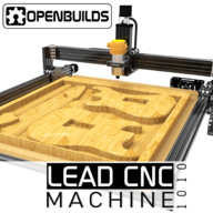
OpenBuilds LEAD CNC

Discussion in 'CNC Mills/Routers' started by MaryD, Nov 20, 2018.

  1. jbhurst

    jbhurst New
    Builder

    Joined:
    Jun 19, 2017
    Messages:
    19
    Likes Received:
    3
    Thanks! All very good suggestions.

    Regarding the wheels, I have had a lot of trouble getting all of the wheels to make good contact, and it is hard for me to reach the eccentric nuts now that the machine is fully assembled with side panels. For example, the wheels that make contact with the X from the Z are not tight in the back since all the weight is on the front with the spindle. I just went back and watched the assembly video again where he explains the wheels should spin some (it looks like under light force), but not freely. By that definition, most of mine are too loose (spin freely) or too tight (very hard to spin manually). Also, when it comes time to replace the wheels, should I look into metal ones?
     
  2. Peter Van Der Walt

    Peter Van Der Walt OpenBuilds Team
    Staff Member Moderator Builder Resident Builder

    Joined:
    Mar 1, 2017
    Messages:
    15,303
    Likes Received:
    4,360
    Correct, you should feel some friction, else it can wobble as they arent preloaded.
    Metal wheels, in turn, turns the rail into the wearable surface (;
    Rather get Xtreme wheels if you do upgrade, they'll last longer than the delrin. But pros/cons the Delrin is more forgiving toward overtightness, the Xtreme ones can crack if tightened too much.
     
  3. jbhurst

    jbhurst New
    Builder

    Joined:
    Jun 19, 2017
    Messages:
    19
    Likes Received:
    3
     
  4. Peter Van Der Walt

    Peter Van Der Walt OpenBuilds Team
    Staff Member Moderator Builder Resident Builder

    Joined:
    Mar 1, 2017
    Messages:
    15,303
    Likes Received:
    4,360
    Springs wouldn't resist a milling load. We use adjustable delrin nuts, when properly adjusted you cannot get backlash
     
    jamin35008 likes this.
  5. jamin35008

    jamin35008 Well-Known
    Builder

    Joined:
    Feb 7, 2019
    Messages:
    136
    Likes Received:
    44
    Is it possible that my X gantry could be slightly off causing tramming issues?

    I went a head a purchased a second router mount and set up my machine like this idea that Medalguru had Extra Strong Double Router Mount

    Even after adding the second mount I'm still finding that the router is off slightly. If I were to put in a large surfacing bit it would be creating steps towards the front of the machine. The bit is lower towards the front.

    Should I use a square to see if the X gantry is square to my waste board? I did surface the board months ago and I didn't have any steps then. Or should I try shimming the Z axis with thin sheet metal or washers to square?
     
  6. Peter Van Der Walt

    Peter Van Der Walt OpenBuilds Team
    Staff Member Moderator Builder Resident Builder

    Joined:
    Mar 1, 2017
    Messages:
    15,303
    Likes Received:
    4,360

    Certainly a sign of tramming issue - which will affect final cut dimensions.

    Watch this video: different machine but the same concepts apply nicely:

    (Basically "square against the bed" isnt good enough. Also has to make sure rails are parallel to bed, and that Z is perpendicular to the XY plane, and then finally that router is square to the Z.

     
    jamin35008 likes this.
  7. jamin35008

    jamin35008 Well-Known
    Builder

    Joined:
    Feb 7, 2019
    Messages:
    136
    Likes Received:
    44
    Very good video Peter. I did make a version of the poor mans spindle gauge and it works very well.

    I feel by adding the second spindle mount and still having the same tramming problem in the same direction as before my X gantry maybe slightly off. What might be the best way to adjust the X gantry? Should I loosen and try and move, loosen and try and move, loosen and try to move kind of thing while I'm testing the levelness with the spindle gauge?
     
  8. Peter Van Der Walt

    Peter Van Der Walt OpenBuilds Team
    Staff Member Moderator Builder Resident Builder

    Joined:
    Mar 1, 2017
    Messages:
    15,303
    Likes Received:
    4,360
    In the video he straightens his X by loosening the side plates, should have enough wiggle in the screw holes to twist a little. May take a try or three to get it perfect
     
    jamin35008 likes this.
  9. jamin35008

    jamin35008 Well-Known
    Builder

    Joined:
    Feb 7, 2019
    Messages:
    136
    Likes Received:
    44
    Perfect! I will give that a try when I get home tonight. Thanks Again!
     
    Peter Van Der Walt likes this.
  10. jamin35008

    jamin35008 Well-Known
    Builder

    Joined:
    Feb 7, 2019
    Messages:
    136
    Likes Received:
    44
    Well I got home loosened the x gantry and adjusted, trammed, re tightened and now when I test the spindle gauge it is as close as its ever been since I started measuring for tram. Great I thought......

    I then decided to measure some distances and see how square everything was after this adjustment and everything looked great until I measured the x gantry from the waste board to the bottom of the x gantry C beam. I got a 1 mm difference between the left side and right side. I'm low on the right side.

    Some thoughts are going through my head...

    1. Was this difference always there so when I surfaced my waste board it just matches the difference in the x gantry?
    2. Is this difference new and now I'm just tramming my router to match the new difference in the x gantry? Which I don't think I want to do.
    3. Should I be measuring the X gantry from something other than the waste board even though its been surfaced?
    4. Try resurfacing the waste board again?
    5. Leave it alone because it only a 1 mm over the whole X gantry and trying to fix that might create more problems.
     
  11. Pelted

    Pelted New
    Builder

    Joined:
    Mar 16, 2017
    Messages:
    26
    Likes Received:
    3
    My LEAD has been working pretty well so far. I'm a bit disappointed in the z height available, and I've dug through some old posts on from the WorkBee and others. Looked at the Cnc4newbie z-axis upgrade, but really I just want to get another inch up from the surface, there is plenty of travel, I just want to get 2" - 2 1/2" stock underneath. It seems the easiest thing to do would be to increase the length of the 20x80 on each side by a little bit to gain this height. What am I missing about just replacing these cut an inch longer?
     
    #581 Pelted, Jul 7, 2019
    Last edited: Jul 7, 2019
  12. jeffmorris

    jeffmorris Journeyman
    Builder

    Joined:
    Nov 6, 2017
    Messages:
    496
    Likes Received:
    115
    I think that it is possible to replace the 20X80X250 extrusions with 20X80X500 extrusions. Before cutting the extrusions, put 2 1/2" stock in the machine, raise the Z-Axis as far as possible, insert a bit in router or spindle, temporarily fasten the extrusions to the machine, leave about an inch of space between bit and stock, remove the stock, and lower Z-Axis as far as possible. The bit should touch the waste board. If not, you'll have to replace the 40X80X250 C-Beam and lead screw with 500mm parts.
     
  13. Pelted

    Pelted New
    Builder

    Joined:
    Mar 16, 2017
    Messages:
    26
    Likes Received:
    3
    I've been sitting here cutting away while building dedicated cart table for the CNC and I had a thought. If I anchor the machine to the bench I can remove the underside 40x20 beams and drop the spoil board onto the bench top below. This would give me 40mm of additional height without really needing to do anything.
     
  14. Stumpy

    Stumpy New
    Builder

    Joined:
    Dec 21, 2018
    Messages:
    37
    Likes Received:
    21
    That sounds like a plan. Only thing I wonder is what the tortion effect would do (if anything)? Those rails probably do more than keep the height at a bare minimum.
     
  15. gregers05

    gregers05 Well-Known
    Builder

    Joined:
    Feb 15, 2019
    Messages:
    131
    Likes Received:
    33
    You guys that are running the makita router, what are you using for dust boots? I originally planned to use the 2 piece magnetic one I found on the projects page, however it hits the Y axis rail a few inches before it gets to X0 position. I am going to try to modify what I have but curious to see what everyone else is doing.
     
  16. Jdubster3d

    Builder

    Joined:
    May 22, 2019
    Messages:
    61
    Likes Received:
    13
    Anyone add anti-backlash nut blocks to their x and y or are they only useful in the Z? Also I just got my Lead 1010 up and running, it runs well and square but when jogging from the front to the back in the y axis i get a fairly loud screeching coming from the screw on the right side of the machine once it hits about halfway. Anyone else experience this? Thanks for any help
     
  17. Jdubster3d

    Builder

    Joined:
    May 22, 2019
    Messages:
    61
    Likes Received:
    13
    Also, anyone add end stops to the x and y, currently running blackbox and think it would take some of the stress out of jogging
     
  18. Rick 2.0

    Rick 2.0 OpenBuilds Team
    Staff Member Moderator Builder Resident Builder

    Joined:
    Dec 20, 2013
    Messages:
    2,899
    Likes Received:
    1,556
    Have you lubricated the screw? I went from a gantry that was way too stiff to one that was easily movable with two fingers with a couple shots of silicon spray.
     
  19. Jdubster3d

    Builder

    Joined:
    May 22, 2019
    Messages:
    61
    Likes Received:
    13
    @Rick 2.0 Thanks for the help Ill give that a shot tonight wasnt sure if that was necessary or if i was just putting a band aid on an underlying problem that someone else may have come across
     
  20. Alex Chambers

    Alex Chambers Master
    Moderator Builder

    Joined:
    Nov 1, 2018
    Messages:
    2,802
    Likes Received:
    1,380
    Use a DRY lubricant @Jdubster3d (silicone or ptfe)
    Alex.
     
  21. sharmstr

    sharmstr OpenBuilds Team
    Staff Member Moderator Builder Resident Builder

    Joined:
    Mar 23, 2018
    Messages:
    2,059
    Likes Received:
    1,449
    You do have them on your x and y already. The double nut blocks take up the backlash
     
  22. Stumpy

    Stumpy New
    Builder

    Joined:
    Dec 21, 2018
    Messages:
    37
    Likes Received:
    21
    I would like to add extra limit switches to X & Y axis as well. My questions are can I hook them in parallel to the existing limit switches or do they need to be hooked in series? Also, will the extra resistance do any harm to the black box?
     
  23. Alex Chambers

    Alex Chambers Master
    Moderator Builder

    Joined:
    Nov 1, 2018
    Messages:
    2,802
    Likes Received:
    1,380
    Normally open switches wire in parallel, normally closed wire in series. The only extra resistance is the wire between them - you will struggle to measure it with most multimeters so it is definitely nothing to worry about.
    Alex.:thumbsup:
     
    sharmstr likes this.
  24. Stumpy

    Stumpy New
    Builder

    Joined:
    Dec 21, 2018
    Messages:
    37
    Likes Received:
    21
    Thanks a lot. I really appreciate the quick response. Now if I can remember I have to refresh the page, I could reply back faster. I plan on using telephone wire (6 part) for the wiring so that should do the trick without taking up too much room. Now if I can get this black box problem solved - but I have to wait till tomorrow to get an answer back from the parts people. Black box reports it can only find smoothie firmware and then shuts down the connection. Life is full of opportunities...
     
  25. Jdubster3d

    Builder

    Joined:
    May 22, 2019
    Messages:
    61
    Likes Received:
    13
    Awww that makes sense! Thank you
     
    sharmstr likes this.
  26. Jdubster3d

    Builder

    Joined:
    May 22, 2019
    Messages:
    61
    Likes Received:
    13
    Thank you for the info guys and such quick responses
     
  27. Peter Van Der Walt

    Peter Van Der Walt OpenBuilds Team
    Staff Member Moderator Builder Resident Builder

    Joined:
    Mar 1, 2017
    Messages:
    15,303
    Likes Received:
    4,360
    Correction: OpenBuilds control tries to deternine the firmware running on a port by first checking if it resets the attached board, if it gets a response. Usually most boards do. If it doesn't then it tries a second time, by sending Ctrl+X. Some boards with autoreset disabled needs this before they resond. Failing to get a response back, it checks if maybe its a Smoothieware based board (we used to sell them so some customers has it)
    Its just 3 steps before giving up. Your board shouldve replied at step 1 but doesnt. Everything after that is just noise for all intents and purposes

    Link to thread about the issue: No firmware found
     
  28. Stumpy

    Stumpy New
    Builder

    Joined:
    Dec 21, 2018
    Messages:
    37
    Likes Received:
    21
    Is there a way to test the boards? Which board has the firmware? I have never had any power going to it but the USB. Could I have burnt out anything if I had incorrect wiring on a stepper motor or limit switch? Only thing I can think of that is possible is a DOA board. I'm sorry to be rambling. Frustration is controlling my thought processes.
     
  29. Peter Van Der Walt

    Peter Van Der Walt OpenBuilds Team
    Staff Member Moderator Builder Resident Builder

    Joined:
    Mar 1, 2017
    Messages:
    15,303
    Likes Received:
    4,360
    Refer to the original thread please, already replied there :) lets not hijack this (the LEAD machine thread) with that, when there is an existing thread
     
  30. Stumpy

    Stumpy New
    Builder

    Joined:
    Dec 21, 2018
    Messages:
    37
    Likes Received:
    21
    Sorry about that. FNG
     

Share This Page

  1. This site uses cookies to help personalise content, tailor your experience and to keep you logged in if you register.
    By continuing to use this site, you are consenting to our use of cookies.
    Dismiss Notice