Welcome to Our Community

Some features disabled for guests. Register Today.

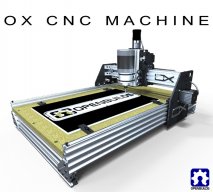
OpenBuilds OX CNC Machine

Discussion in 'CNC Mills/Routers' started by Mark Carew, Dec 15, 2013.

  1. Rick 2.0

    Rick 2.0 OpenBuilds Team
    Staff Member Moderator Builder Resident Builder

    Joined:
    Dec 20, 2013
    Messages:
    2,892
    Likes Received:
    1,551
    @chadderuski, that distance should come up in the 85.9 to 86.1 range. You may have a set of the version 8.0 Ox plates which did have the holes a bit too close, something that has since been rectified on the V8.1 plates. Drilling out the smaller, non-eccentric holes to 7mm (9/32") should give you the clearance you need. Just be sure the non-eccentric bolts are all the way to the outside of the hole prior to tightening them.
     
  2. chadderuski

    Builder

    Joined:
    Feb 13, 2015
    Messages:
    11
    Likes Received:
    4
    Hi Rick,

    Yes, my plates were cut using v8.0 planes. I failed to not that I am using the Xtreme Solid V Wheels which have MUCH less give the the standard wheels so this may also be giving me trouble.

    What is the new distance in the v8.1 plates to the outside edge of the holes?

    Thanks!
     
  3. Rick 2.0

    Rick 2.0 OpenBuilds Team
    Staff Member Moderator Builder Resident Builder

    Joined:
    Dec 20, 2013
    Messages:
    2,892
    Likes Received:
    1,551
    The drawing measures to 85.8685mm. This is based on c/c hole spacing of 79.8 and drawn holes of 7.1370 & 5.0mm diameter. The holes in reality are generally a bit larger than this. The 79.8mm c/c spacing is also on the minimalist side. I would typically use 80mm.
     
  4. chadderuski

    Builder

    Joined:
    Feb 13, 2015
    Messages:
    11
    Likes Received:
    4
    Okay, finally get to post some good news. I was able to get my holes outer distances to 85.4 mm (give or take hair), and this work just right. This is with the offset nuts at their widest. The rail went on
    with just a "bit" of a push and roll smoothly now. NOT freely, just smoothly like they have just the right amount of friction.

    For the cross beams I was able to use a disc sander to true-up the one cut that was bad. Once I put the gantry all together everything squared up quite nicely.

    Rick, what software are you using to view the drawings? Everything I've tried so far just show me the outlines and no dimension.

    Thanks again for everyone's help!
     
  5. Rick 2.0

    Rick 2.0 OpenBuilds Team
    Staff Member Moderator Builder Resident Builder

    Joined:
    Dec 20, 2013
    Messages:
    2,892
    Likes Received:
    1,551
    I have a copy of Autocad. And no software will simply show dimensions unless someone has intentionally put them on there (which isn't the case here). You have to either go in and dimension them yourself or go in and take measurements. You can do the latter with Autodesk Trueview which is freeware but it is very cumbersome. There may be other programs out that will do this a lot easier but I can't offer any specific direction as I have never had the need to look into them.
     
  6. Rob Mitchell

    Rob Mitchell Well-Known
    Builder

    Joined:
    Nov 29, 2015
    Messages:
    105
    Likes Received:
    35
    If I use the parts list (parts tab above) what dimension and usable cutting surface will I end up with?
     
  7. Lstj

    Lstj New
    Builder

    Joined:
    Sep 24, 2015
    Messages:
    15
    Likes Received:
    0
    hello, i have a question
    why cut results not accurate (less than 1mm)
    ex: cut 50mm x 30mm, result 49mm x 29mm
    but from mach3 (setting alt6) really accurate
     
  8. Jestah

    Jestah Well-Known
    Builder

    Joined:
    Dec 4, 2013
    Messages:
    148
    Likes Received:
    84
    Could you please give us a little more info about the setup you are having issues with?

    A stab in the dark says that your first setup may have incorrect steps per value. Try copying the Mach3 steps per into the first system and see if your accuracy increases.
     
  9. Lstj

    Lstj New
    Builder

    Joined:
    Sep 24, 2015
    Messages:
    15
    Likes Received:
    0
    i use RnP,
    pinion pitch diameter 21 mm, 14 teeth
    motor 200 step/rev, 10 microstep
    mach3 setup motor tuning 30.33 step per mm, acc 4000, velo 500
     
  10. David the swarfer

    David the swarfer OpenBuilds Team
    Staff Member Moderator Builder Resident Builder

    Joined:
    Aug 6, 2013
    Messages:
    3,460
    Likes Received:
    1,915
  11. Designut

    Designut New
    Builder

    Joined:
    Dec 5, 2015
    Messages:
    1
    Likes Received:
    0
    What grade of garolite are you using and where do you get it from?
     
  12. jeremym87

    jeremym87 New
    Builder

    Joined:
    Oct 28, 2015
    Messages:
    1
    Likes Received:
    1
    Just received my Plates - I'm ready to build! Thanks for the great project idea! I'm going with a 1000 x 1000 to start, might scale up the Y to a full 1500 if I have a need for it.
     
    Chris Laidlaw likes this.
  13. souprmage

    souprmage New
    Builder

    Joined:
    Sep 2, 2015
    Messages:
    26
    Likes Received:
    5
    <I'm just going to apologize for the novel now, but I read this entire thread in the last week, and you can all read my long winded post :p>

    By some miracle, I've managed to read the entire 103.5 pages of this thread since past Thursday. Thank goodness that's over with. I think I grabbed enough information from posts along the way that may prove useful in the near future without having to go back and search for things. Crossing my fingers.

    I got hooked on this site last year while researching 3-D Printers and found the C-Bot. With little CNC knowledge and background, I decided to get a OpenBuilds Pegasus 8" after someone on that thread suggested it as a good way to get started learning. It took me a few weeks to sort through some minor issues with the build, but now I can reliably print parts that I'd otherwise have to do without. The printer has really been worth every penny. It's so good though, I may not get around to building the C-Bot, which isn't helped because now the OX has pulled me in.

    While I have fewer immediate projects planned for the OX, I have no end of areas that I could discover more uses. My hobbies include SimRacing and karting, those alone will provide ample inspiration as I get more comfortable designing parts and what's possible. I also have a small farm which is always in need of something needing repair. The welding table you see in my profile pic is a recent build after having purchased a MIG welder recently. It'll provide a great build/work surface for the OX, with a 1/2" steel top.

    I saw the first post on this thread and since I'm in the US and I didn't want to deal with parting everything individually, I decided to check out the kit from SMW3D. A few YouTube channels I frequent have an X-Carve, but comparing that to the OX seems like apples and oranges. The X-Carve would probably prove useful, but it's rails just seem too small to be useful for all the projects I am anticipating. So even though the OX kit is more expensive I think it's worth it.

    I wanted the kit by X-Mas so I can build it during the holiday's, so I made the snap decision to get the kit without knowing for certain if their kit is good quality nor if their support was going to get me up and running quickly. One person about 15-20 pages back had an issue with the completeness of their directions (from the electronics side), as well as their responsiveness, and I'm hoping this isn't the norm. Setting up the software and CAM side of things is going to be my weak point and will certainly need help here, but you all seem able to help even if the vendor isn't responsive. I am planning on doing the same implementation that person did, with a Raspberry Pi and Chillipepr. I use the Raspberry Pi and OctoPrint with my printer, and it works great.

    I got every option added to the kit, so it's a 750x1000 and I'll see about doing a build blog for that once I get started. Part of me wishes I had the 1m/1.5m like a lot of you have, but I also know the smaller gantry will probably make things more reliable/repeatable without having to add additional support. So, it's both good and bad. Would be nice to have a 2'x4' work area, but I could expand it later if I need it bad enough.

    The questions I have for all of you that have an OX and have been using it for a year or more. How reliable has the machine been for you? What amount of maintenance has it required? Like tightening belts/bolts, or recalibrating steps, etc. A few of you seem to still be active, but a number of early posters are not around now. Have people moved on from the OX? Has some better design popped up that has gotten people's attention? (ie. was my quick decision to buy the kit without getting the above answers a mistake)

    I have a question on how to create a plastic part with a grove for a 32mm pipe to fit in, but I'll take that to a different thread as it's off-topic here.
     
    EdinSimon likes this.
  14. David the swarfer

    David the swarfer OpenBuilds Team
    Staff Member Moderator Builder Resident Builder

    Joined:
    Aug 6, 2013
    Messages:
    3,460
    Likes Received:
    1,915
    you mean a circular groove? how thick is the wall? how wide is the cutter bit?

    I would: (In Sketchup of course :)
    draw a circle for the inside of the pipe
    draw a circle for the outside of the pipe
    do an offset from the inside circle toward the outside, half the cutter diam
    do an offset from the outside circle toward the inside, half the cutter diam
    is the gap between them wider than the cutter?
    if so, add some more offset lines to fill the gap.

    set all the offset lines to 'centerline cut' at 100% deep (not the inside and outside 'pipe' lines)
    set the material thickness to how deep I want the groove.
    (you can set the 0,0 offset here if you like, so make positioning the cut on the part easier)
    generate Gcode.
    cut
     
  15. souprmage

    souprmage New
    Builder

    Joined:
    Sep 2, 2015
    Messages:
    26
    Likes Received:
    5
    this, but just pretend the chamfer goes all the way around the top edge (it would also be on the bottom edge, but that would just take flipping the part and doing the same as is done for the top chamfer). So, a V-bit for the chamfer and I was thinking a round bit would work best for the 'dip'. I'm new to machining, I imaging there's a technical term for this, so pardon my ignorance.

    [​IMG]
     
  16. David the swarfer

    David the swarfer OpenBuilds Team
    Staff Member Moderator Builder Resident Builder

    Joined:
    Aug 6, 2013
    Messages:
    3,460
    Likes Received:
    1,915
    you had to go and choose THE hardest thing to do (-:
    that groove is really a 3D part, and currently the 3D module does not cut the correct size.
    I recommend using PyCAM
    and you will need an STL output plugin.

    if I were doing this for myself I would just do it 'manually', figure out the first cut line in Gcode then I'd write a little script, probably in php, to take that first line and offset it by some amount till it gets to the other side of the part.
    in fact I might create the cut line in SketchUcam, then let the script rotate it into the vertical plane (from XY to XZ) AND offset it for me along Y.

    on the other hand, the chamfer is quite easy. you do not want to cut with the point of the tool, but rather further up the flutes, it is more efficient.
    I do a simple drawing of the tool, and the edge of the part, depicting the size of the chamfer I want, and from that measure the depth the tool needs to cut, and also the offset of the center of the tool from the edge of the part.
    now I set the depth as the 'material thickness' and the offset*2 as the bit diameter and add an outside cut to the part (or inside if needed) and generate Gcode for that cut. you cannot do any other cuts at the same time, but you can watch my videos on multipart drawings to see how to do that.

    I had a bit of paper here where I had worked out some formulas for doing this, but it has gone missing and doing a drawing is just as easy (for me).

    the blue is the cutter profile, the red is the part in edge view.
    part edge to tool center is 3mm so set the tool diameter to 6mm, and material thickness to 3.5mm (and overcut% to 100%)
    and this will give a 2mm wide chamfer on the part. you can just vary the depth to get more or less chamfer.
    chamfer2.png
    I recently did exactly this on a part that needed a deep inverted V in the middle of the part. 2 chamfer cuts with different offsets and depths got it done.
    IMG-20151113-WA0007A.jpg
     
    Kyo and Mark Carew like this.
  17. souprmage

    souprmage New
    Builder

    Joined:
    Sep 2, 2015
    Messages:
    26
    Likes Received:
    5
    excellent, I figured the chamfer would be a simple plunge cut. So it sounds like the offset out is easy enough to do, then just a matter of figuring out how far down I need to go, taking small passes as I go. I was originally thinking I could just print this part using ABS and it would be 'good enough' for a while, but getting the OX, I may as well make it as good as can be. The part is for a skid plate on the bottom of my kart. It keeps the frame from being wore through over time. The ones you buy are delrin and about $60 a set of 3. I should be able to buy a large enough sheet of delrin to make 3-4 sets for that amount easy.

    The conclusion I came to was the 'trough' was going to require full 3d shaping, glad to know I wasn't missing something. The 3d options seem to have a broad array of capability between them. I'm still trying to find that 'right' tool that can do all the things I can envision and even the ones I can't. I'm going to try to learn Fusion 360, if for no other reason than I want to broaden my horizons. But things I can do in no time at all on SketchUp are more tedious on Fusion 360. Although I'm sure that's just because of lack of seat time. I'm not opposed to spending a few hundred dollars on solution here, but if I do, I want to get the best one for my needs as I don't want to get more than one. but with the v-bit carving stuff, that's pretty cool as well. There's just so many cad options out there it makes your head spin.

    I'm guessing once I make a program for the chamfer and one for the 3d carve, I'll be able to merge them together so I can cut them out in a single go, with pauses between them to change the tool and re-zero and resume?

    I've now discovered bCNC as an option for driving the OX, and I really like that solution better as I can install that right on the Raspberry Pi and not have to have a separate computer running the client. It means all I need is a screen and mouse plugged into the Pi that's plugged into the OX and it's self contained.

    PS. I've already watched all your videos. It's part of what took me all weekend to 'read' this thread. ;) Thanks for your contributions to the community.
     
    David the swarfer likes this.
  18. Rchobbysuk

    Builder

    Joined:
    Aug 13, 2015
    Messages:
    3
    Likes Received:
    0
  19. EdinSimon

    EdinSimon New
    Builder

    Joined:
    May 14, 2014
    Messages:
    2
    Likes Received:
    3
  20. souprmage

    souprmage New
    Builder

    Joined:
    Sep 2, 2015
    Messages:
    26
    Likes Received:
    5
    Re-quoting the bit that remains unanswered. I'm guessing by the lack of responses, it answers the question though. Now I'm curious what people have moved on to. Hopefully it doesn't require a rebuild of the kit I just bought.
     
  21. Steve Fox

    Steve Fox Well-Known
    Builder

    Joined:
    Feb 22, 2015
    Messages:
    129
    Likes Received:
    21
    Why would you assume that people have moved on?

    One, I don't believe that there are that many OXes (OXen?) out there more than a year old.
    Two, if they are like mine, they haven't needed any maintenance.
    I built mine about eight months ago and haven't had any maintenance issues.
    I've spent time improving it, but because I wanted to, not because I needed to.
    If there are any issues I am aware of, it would be the type of wheels you use and how the Z-Axis is attached.
    The current design isn't quite as rigid on the Z-Axis as I think it should be.
    I intend to change mine to use the C-Beam bundle. It now appears I will mount it backwards as has been discussed in another thread.

    If others are like me, I spend a lot of time on a given forum when I build a project, but very little time after it's completed.

    It could be that other builders are similar. Call it selfishness or whatever, but people lose interest after a while and don't always give back as much as they get.

    Right now, I'm in the process of gathering parts for a Rotary OX.
     
  22. souprmage

    souprmage New
    Builder

    Joined:
    Sep 2, 2015
    Messages:
    26
    Likes Received:
    5
    Only because I posed the questions last week and no responses on that aspect. But you're right, it's assumptive of me to conclude they've moved on.

    Although browsing around, it does seem the recent trend is to use c-beam instead of belts for more accuracy, esp. for aluminum. But I'm sure the belts will be fine for my purposes for now. I will be doing some aluminum, but it doesn't need to be accurate and fast, I'll just slow me feed/speed rates as others have mentioned.

    I appreciate the response and am glad to know you're happy with the OX. I'll be like you, constantly fiddling with it to make it better. Just like I do for my 3-d printer. I think I spend more time making parts for the printer than anything else. But that's part of the fun, and I don't do this for any other reason, so it's all good.
     
  23. Steve Fox

    Steve Fox Well-Known
    Builder

    Joined:
    Feb 22, 2015
    Messages:
    129
    Likes Received:
    21
    Several years ago, I came to the conclusion that I am a tool maker.
    I spend much more time making the tools than making the end parts, no matter what the hobby.

    I wonder if there's a support group for us?
     
    Jestah and David the swarfer like this.
  24. snokid

    snokid Journeyman
    Builder

    Joined:
    Oct 11, 2014
    Messages:
    335
    Likes Received:
    104
    Mine is right around a year old.
    Gets used monthly
    belts haven't given me a problem.
    Sure it's not rigid as some, it also doesn't cost what some do.....
    aluminum will be no problem I find that depth of cut matters more than the speed.

    I'm in the camp of upgrading mine also to the c-beam style.
    I already have a c-beam machine also. (can't be up north most of the summer without a cnc!!!LOL)
    Wife just gave up, she knows I'm nuts!!!!
    Bob
     
    Mark Carew likes this.
  25. souprmage

    souprmage New
    Builder

    Joined:
    Sep 2, 2015
    Messages:
    26
    Likes Received:
    5
    This is it Steve, our support group is here. Thank goodness. Although my wife is used to my obsession of the month, but the bills are paid, so it keeps her happy. At the end of the day, that's the most important thing.

    I guess I'll do the aluminum for now and see how much I end up using it for these sorts of parts. If it's enough, I'll likely upgrade to the c-beam as that seems like a logical progression. But for now, I'll cut my teeth with belts and see where it leads. I don't think I could live without my 3d printer at this point, hopefully this ends up the same.
     
  26. Jay_r

    Jay_r New
    Builder

    Joined:
    Apr 18, 2014
    Messages:
    10
    Likes Received:
    2
    I've had mine for about a year and a half. Mechanically, its been ok. The Z like to work it self loose. But, I machined my plates on an earlier drawing. I suspect that the new drawings have the bolt hols for the spacer closer together. The other axises, Ive only snugged up now and again. The only thing that Ive upgraded are the belts. The GT3 belts should be standard as the stock ones tend to slip. But, I am pushing a 1.5 kw spindle around with 380Oz steppers and I push it hard. So, it may be a self induced problem.

    It is very possible that people have moved on. I'll be moving on soon. The OX has served me well as a springboard to learning and enjoying the cnc hobby. My projects are getting larger and more complex and need a larger more rigid machine.
     
  27. souprmage

    souprmage New
    Builder

    Joined:
    Sep 2, 2015
    Messages:
    26
    Likes Received:
    5
    Great feedback Jay. I did get the GT3 belt upgrade on my kit, so that's good.
     
  28. chadderuski

    Builder

    Joined:
    Feb 13, 2015
    Messages:
    11
    Likes Received:
    4
    Hi All!

    Have made a lot of good progress on the OX. I have all axis up and running and home switches for the x and y working, but I am having trouble figuring out the best way to install the z-axis homing switch.

    My switch is the omron (see attached).

    Suggestions?

    V-156-1C25-Omron.jpg
     
  29. Neptunes Guitars

    Builder

    Joined:
    Apr 5, 2015
    Messages:
    11
    Likes Received:
    9
    Hi mate have a look at the Stainless Steel Ox by Martin that's how mounted my Z switch albeit I bolted mine on. I elongated one hole to allow for adjustment up and down to fine tune it.
    Good luck chadderuski
    Cheers,
    Peter
     
  30. Florian Bauereisen

    Florian Bauereisen Well-Known
    Builder

    Joined:
    Feb 24, 2014
    Messages:
    188
    Likes Received:
    60
    Hi,
    @chadderuski
    try to source the (same-) kind of switches with shorter arms...
    The lesser lever will give you better accuracy. Think of it.
    I think mine are from omron too..

    greets

    Flo
     

Share This Page

  1. This site uses cookies to help personalise content, tailor your experience and to keep you logged in if you register.
    By continuing to use this site, you are consenting to our use of cookies.
    Dismiss Notice