Welcome to Our Community

Some features disabled for guests. Register Today.

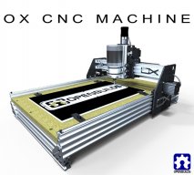
OpenBuilds OX CNC Machine

Discussion in 'CNC Mills/Routers' started by Mark Carew, Dec 15, 2013.

  1. sgspenceley

    sgspenceley Veteran
    Builder

    Joined:
    May 27, 2014
    Messages:
    249
    Likes Received:
    292
  2. James Gao

    James Gao New
    Builder

    Joined:
    Feb 21, 2015
    Messages:
    14
    Likes Received:
    25
    If you really want to go ultra-budget, I've had pretty good luck modding a standard RAMPS board to fit onto an Arduino Due running TinyG2. You can get a RAMPS board + 5 DRV8825 drivers on ebay for about $16 these days, and the arduino for about $23. The DRV8825 drivers only handle 2A of current, but with a 24V supply, that should be plenty to drive NEMA23's.

    TinyG2 also supports using serial-json-server, so you could drive the CNC remotely by attaching the Due to a raspberry pi.
     
  3. Kevon Ritter

    Kevon Ritter Veteran
    Builder

    Joined:
    Apr 30, 2015
    Messages:
    597
    Likes Received:
    294
    Hey everyone,
    This is my first post here so be gentle. :oops:

    Disclaimer: I did try searching, but could not come up with much.

    I have only recently found the OpenBuild hardware, but have been looking at it nonstop for the past few days. I like the idea of using lead screws over belts, but noticed that this is mostly catered to...belts. There are plenty of people here with Ox based machines so belts can't not (yes I know) be working.

    My other hobbies include RC planes (cars, boats, helis, all of it), aquariums, and full size cars. I make parts for all of it, but am tired of outsourcing every little idea I have.

    This is where my concern comes in to play. My materials of choice would be varies foams (3D and 2D), carbon fiber and fiberglass (2D), copper clad circuit boards, and softer woods HDF/MDF. If I'm building it, I would want a 1.5'x3'cutting area at the minimum. I decided that I would go with a 750mm Y-axis with a 1000mm X-axis, not travel distance for , but length of the actual parts. It would also be a budget build so I can't see anything more than 1/32 micro stepping.

    How accurate and precise would this be? Time is no concern. I would wait hours to get something done precisely if I had to, but can the mechanics do it? Or is this a job for a much more expensive machine? :cry:
     
  4. James Gao

    James Gao New
    Builder

    Joined:
    Feb 21, 2015
    Messages:
    14
    Likes Received:
    25
    I recently tried 2lb polystyrene hobby foam, which I assume is what RC planes use. It milled absolutely beautifully, I was taking 5mm depth passes and everything was spot on according to my cheap micrometer. I built my ox derivative from laser-cut acrylic plates, so it's significantly less stiff than the aluminum plates. To give you an idea of the accuracy possible, I just milled pockets for 1/4" magnets in a sheet of HDPE, and the magnets are a press-fit. I have DRV8825 1/32 microstepping drivers on my controller.

    Over long enough stretches, you do find a small amount of imprecision. I suspect it's due to a minor amount of belt stretch and/or flex in my crappy acrylic plates. By minor, I mean I found 0.2mm error after milling 50mm of 1/8" aluminum, and I haven't attempted to compensate for the size yet. There are videos of people who have successfully milled TQFP packages using the Shapeoko, which has a very similar design.

    I suspect that something like the OX is only a limitation in three cases -- when you need micron accuracy, if you're trying to mill hard metals, or if you need multi-axis milling of very large objects. If your models can be cut from 1-2" sheets of soft material, then the ox will be great.
     
    Mark Carew, Rick 2.0 and Kevon Ritter like this.
  5. Kevon Ritter

    Kevon Ritter Veteran
    Builder

    Joined:
    Apr 30, 2015
    Messages:
    597
    Likes Received:
    294
    Thank you. That's exactly the kind of answer I was looking for.
     
  6. rfraties

    rfraties New
    Builder

    Joined:
    Jan 23, 2015
    Messages:
    4
    Likes Received:
    0
    Hi Everyone,

    OK, so I just recently completed my OX build -- for the large size OX.

    Attached is a picture of the X/Z assembly.

    There were a few glitches while building it.

    The first was that I initially stripped my ACME block. The threaded rod did not fit quite right. I was trying to "loosen it up" using a drill and ended up melting the plastic. Then ordered a new one and it was OK. I might suggest buying and mounting two ACME blocks, rather than one. As you can see in the attached picture. I had to drill some new holes. And getting everything aligned perfectly was a bit tricky. It turns out that the lower block, if I tighten it all the way, the rod will have too much friction. So if I loosen it just a bit (the screws, holding the acme block in place), then the friction on the rod is just right.

    The second was that I burned out my controller card (smoke, smoke, snap, crackle, pop), because I failed to reset the voltage input on my power supply to 115v from the factory default 230v. Ended up buying a second card.

    Another key issue was the wiring. I put all the electronics in a separate box. I want to be able to remove the controller box so that I hang the machine on the wall when not in use. So I need removable connections on all the wires. I first tried molex connectors but found I could not crimp them reliably. Ended up using single wire crimping connectors. It works, but it is not very pretty, and 16 connectors in total, plus two for the spindle. Having put it all together now, I think there is a better way: Start out with 4 Ethernet patch cables, CAT-6, six foot each (or longer, if you like), in four different colors (one color for each motor). Also purchase 4 female to female patch cables, 3 feet each, also in different colors (a rare item, you would have to buy it online). (Alternatively, you could also use Ethernet extension cables (with a male on one side and a female on the other). The point is to have two males and two females in each of four different colors.) Cut the short cables in half. There are eight wires in each cable, but they are thin. Use two Ethernet wires for each wire on the motor. Strip them (carefully!), twist them and solder them to the motor wires. With the other half of the short cable, strip and twist each pair of wires. Now each of the four the twisted pairs will go into your controller, for a single motor. Now you have a connector at the motor, and a connector at the controller card. Finally, use the long cable to connect them, and use cable-ties to lock everything down. Now you can disconnect the controller box easily. Also you can remove a single motor easily if you need to do maintenance. A bit complicated I know, but I think the result could be decent. The advantage of the Ethernet cables, is that you would not have to do the connectors yourself -- you just buy the patch cables and the connectors are already on there.

    Presently, I am testing out the machine and working out the kinks, and experimenting with the software. (TinyG).

    I am presently trying to level out the spoiler board. I am finding that the z-axis will drift, during each cut.

    I find that the z-axis, if I push the axis down using light finger pressure, the rod will actually spin, and the axis will drop down.

    The z-axis does not wiggle or vibrate at all, I have put it together very carefully, it is quite tight in fact. It is loose only in the sense that you can push it and the rod and the motor will spin. Note that I have greased the rod, using heavy bearing grease.

    So if the router bit grabs into the wood, it will pull the z-axis down. This is an up-cut bit, and so will tend to pull down. Additionally, the bit will also pull the Y-axis, and I will get it to drift there as well.

    I know I can slow it down, the feed rate. And probably also use a smaller bit. But this is a big board. I am not interested in a 12-hour job just to level off the board. Want to pass back and forth quickly and get it leveled quickly.

    Any ideas?

    Probably a down-cut bit causes the z-axis to push up, rather than down. That might help. For some unknown reason, if I push up on the Z, the rod will not spin and the motor will not spin. It only spins if I push it down.

    So that takes care of Z and presumably also Y. Because if it does not dig into the board, then it may not pull on the Y.

    I am thinking that limit switches are probably almost a necessity. Probably should be part of the standard build list. You need them to protect your machine from going past a limit. Additionally, you also need them to sync or reset your position. By sending a move command past the limit, the machine will stop right at the limit. So it is a reliable way to put any axis back to a known position. Which is essential if you are getting any kind of drift during a cut. You can add some re-syncs to your cut program, on whichever axis is drifting.

    Thanks.
     

    Attached Files:

  7. James Gao

    James Gao New
    Builder

    Joined:
    Feb 21, 2015
    Messages:
    14
    Likes Received:
    25
    What controller board are you using? You should have it maintain current to the Z stepper during X/Y moves. In TinyG, you'll want to send $3pm 1 to have the Z-axis be "always on".

    Also, I was under the impression that grease on delrin was a bad idea. Grease tends to make plastic disintegrate.
     
  8. rfraties

    rfraties New
    Builder

    Joined:
    Jan 23, 2015
    Messages:
    4
    Likes Received:
    0
    James,

    OK, the Z-axis always-on should probably help quite a bit. Thanks for the tip!

    From Dupont web page:

    Common features of Delrin acetal resins include mechanical and physical properties such as high mechanical strength and rigidity, excellent fatigue and impact resistance, as well as resistance to moisture, gasoline, lubricants, solvents, and many other neutral chemicals. Delrin® acetal resins also have excellent dimensional stability and good electrical insulating characteristics. They are naturally resilient, self-lubricating, and available in a variety of colors and speciality grades.

    Looks like it should be OK with grease as long as it is not acidic.
     
  9. rfraties

    rfraties New
    Builder

    Joined:
    Jan 23, 2015
    Messages:
    4
    Likes Received:
    0
    OK, I will look into those fly cutters. Thanks!
     
  10. Joe Santarsiero

    Joe Santarsiero OB addict
    Staff Member Moderator Builder

    Joined:
    Oct 30, 2014
    Messages:
    902
    Likes Received:
    196
    There may be concern with grease and oils on the polycarbonate wheels, but not on the delrin.
     
  11. Kevon Ritter

    Kevon Ritter Veteran
    Builder

    Joined:
    Apr 30, 2015
    Messages:
    597
    Likes Received:
    294
    The main concern with grease is the fact that it attracts foreign material.
     
  12. rfraties

    rfraties New
    Builder

    Joined:
    Jan 23, 2015
    Messages:
    4
    Likes Received:
    0
    Joe, Kevin,

    OK, good points on the grease. I will keep an eye on that.

    Thanks again.
     
  13. Donald D. Parker

    Builder

    Joined:
    Jan 26, 2014
    Messages:
    20
    Likes Received:
    13
    Prior to applying grease or petroleum lubes to plastics check the data sheet. Many plastics are compatible with petroleum but many are not. eg put gasoline in a styrofoam cup... Don't assume that your $8.00 polycarbonate wheel won't die a cruel death...
     
    Joe Santarsiero likes this.
  14. Mopar32985

    Mopar32985 Well-Known
    Builder

    Joined:
    Dec 7, 2013
    Messages:
    128
    Likes Received:
    47
    So i wanted to get some input from you guys. My hobbycnc board has to go so im in the market for a new controller. My steppers are 8 wire and need 3a output for motors. I would prefer a parallel port to controll. My budget is $350. Any help would be greatly appreciated. Also im using Mach3
     
  15. Joe Santarsiero

    Joe Santarsiero OB addict
    Staff Member Moderator Builder

    Joined:
    Oct 30, 2014
    Messages:
    902
    Likes Received:
    196
    What power supply do you have?
     
  16. Mopar32985

    Mopar32985 Well-Known
    Builder

    Joined:
    Dec 7, 2013
    Messages:
    128
    Likes Received:
    47
    I have a 24v power supply
     
  17. Joe Santarsiero

    Joe Santarsiero OB addict
    Staff Member Moderator Builder

    Joined:
    Oct 30, 2014
    Messages:
    902
    Likes Received:
    196
    A lot of people will recommend the gecko g540. Its plug and play and below your budget. Depending on your steppers you might want to throw the extra cash at a 36 or 48v PS.
     
  18. Mopar32985

    Mopar32985 Well-Known
    Builder

    Joined:
    Dec 7, 2013
    Messages:
    128
    Likes Received:
    47
    Great thanks for the input thats the one i have been looking into. I think that is the route i will go. The last controller i had to solder all the componets onto the pcb board so plug and play sounds good. I will look up and make sure it will support my 8 wire motors. Also what will jumping up the voltage help with. My steppers are a little over 300oz and only need about 3amps. Thanks again man!
     
  19. Joe Santarsiero

    Joe Santarsiero OB addict
    Staff Member Moderator Builder

    Joined:
    Oct 30, 2014
    Messages:
    902
    Likes Received:
    196
    Nothing wrong with a build it yourself board. Its good experience and rewarding when working correctly. You shouldnt have a problem with 8 wire stepper steppers. Bumping up the voltage will make them "snappier"...
     
  20. Mopar32985

    Mopar32985 Well-Known
    Builder

    Joined:
    Dec 7, 2013
    Messages:
    128
    Likes Received:
    47
    This is true man it was a fun kit to put together and helped teach me how to test a board and check for breaks. Well i just placed an order for the Gecko g540. I cant wait to get this installed. Seems like people love it from what i have read online.
     
  21. Joe Santarsiero

    Joe Santarsiero OB addict
    Staff Member Moderator Builder

    Joined:
    Oct 30, 2014
    Messages:
    902
    Likes Received:
    196
    Yeah. The G540 is all the hype. Personally, I went with an MX4660 because my machine might need more umph later on.
    Congrats on the new purchase/upgrade. Dont forget the db9 connectors and figuring out resistors for motor connects.

    Happy chip making.
     
  22. Josh B

    Josh B Well-Known
    Builder

    Joined:
    Nov 4, 2014
    Messages:
    116
    Likes Received:
    42
    Anyone using one of the 400W- 48v-12,000rpm spindle from China fleabay, to cut balsa and light ply airplane parts? If so, could you share your feeds and speeds with me? I'm cutting on a large OX with all standard OB parts, dual belts on all axes and an XPro V2 controller.
    My design path is as follows: Draftsight --> SU8 --> Sketchucam --> GRBL Controller (sometimes UGCS) . I've tried all kinds of bits, my latest will be diamond cut bits found at Midwest Circuit Technology, when they arrive. I'm using 1/16" and 1/32" bits, I want the fine detail of the ribs and formers and I don't mind the wait of cutting slow. Should I be using a different style bit? I've read lots of different opinions on this, Up cut, Down cut, "O" flute, single flute, double flute.....I'd like to stick with the diamond cut bits if possible, I'm just having a heck of a time finding the correct F&S setting.

    PS - I've tried different F&S calculators but can't find one that has balsa or baltic birch ply cutting material option. OP, let me know if this reply needs to be posted elsewhere.

    Josh
     
    #2392 Josh B, May 6, 2015
    Last edited: May 6, 2015
  23. Krishnakumar

    Builder

    Joined:
    Nov 25, 2014
    Messages:
    27
    Likes Received:
    13
    Hi Josh,
    I have attached a Dremel 3000 to my CNC with a 1mm (0.4") diamond cut router bit (from www.drillbitsunlimited.com) for cutting balsa and 3mm basswood/plywood. My settings are 50mm/min with 2 passes. Its takes very long time but since I am only cutting motor mounts, it works fine for me...
    I have lost a lot of 1/32" bits as they just cannot handle the tension while cutting wood. The thickness of 0.4" bits seems to be working perfectly for me. Just make sure to do more than 2 passes or else the bits will break...
    I suspect you could use about 75mm/min for 1/16" bits.

    Good Luck!
     
  24. Josh B

    Josh B Well-Known
    Builder

    Joined:
    Nov 4, 2014
    Messages:
    116
    Likes Received:
    42
    Thanks Krishnakumar, what rpm are you running your spindle while cutting 50mm/min? I kinda feel limited with this spindle at a 12000 rpm max.
     
  25. Krishnakumar

    Builder

    Joined:
    Nov 25, 2014
    Messages:
    27
    Likes Received:
    13
    I think I am somewhere in range of 15000rpm... But I think 12000rpm would work just fine...
     
  26. Mopar32985

    Mopar32985 Well-Known
    Builder

    Joined:
    Dec 7, 2013
    Messages:
    128
    Likes Received:
    47
    Well i got my new Gecko G540 controller intoday and very excited to get it set up. Im having a bit of trouble finding out how to hook the motors up to the connectors. I have 8 wire stepper motors but have the down to 6 for the hook up to the hobbycnc board ( pics below ). I have B b com com a A also my nema 23 are 3 amp and my nema 17 is 1.2. So i know i need to add a 3k resistor from pin 1 to 5 and a 1.2k resistor for the nema 17. Also i an see the a coils go to pins 9 and 8 and B coils go to 7 and 6 but i have no idea what i do with the comm. Any help would be greatly appreciated
     

    Attached Files:

  27. Tweakie

    Tweakie OpenBuilds Team
    Moderator

    Joined:
    Jan 18, 2014
    Messages:
    784
    Likes Received:
    326
    Mark Carew likes this.
  28. Mopar32985

    Mopar32985 Well-Known
    Builder

    Joined:
    Dec 7, 2013
    Messages:
    128
    Likes Received:
    47
    Thanks man i have found this before to but still very confused as to tell what wire is which i know what wites are b coil and a coil but not sure where i need to put the remaining 4 wires. Right now i only have 6 wires hooked to my old driver b3cause i combined 4 com down to 2 com wires. Sorry i can follow directions but not good at understanding the diagrams. Im a little paranoid to mess something up
     
  29. Mopar32985

    Mopar32985 Well-Known
    Builder

    Joined:
    Dec 7, 2013
    Messages:
    128
    Likes Received:
    47
    OK so i found the data sheet for my stepper does this look right to you guys a coil on left b coils on right. Again any help would be greatly appreciated. Also i have a 24v powersupply and ran these fine on my hobbycnc board do i have to step it up to a 48v system
     

    Attached Files:

  30. Tweakie

    Tweakie OpenBuilds Team
    Moderator

    Joined:
    Jan 18, 2014
    Messages:
    784
    Likes Received:
    326
    That looks just perfect :thumbsup:
    Set your drivers for 2.8 amp max. current (resistor values) and away you go.

    Tweakie.
     
    Mopar32985 likes this.

Share This Page

  1. This site uses cookies to help personalise content, tailor your experience and to keep you logged in if you register.
    By continuing to use this site, you are consenting to our use of cookies.
    Dismiss Notice