Welcome to Our Community

Some features disabled for guests. Register Today.

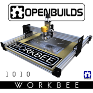
OpenBuilds WorkBee 1010

Discussion in 'CNC Mills/Routers' started by Mark Carew, Jun 15, 2018.

  1. stargeezer

    stargeezer Journeyman
    Builder

    Joined:
    Feb 20, 2015
    Messages:
    328
    Likes Received:
    117


    Hi Torr,

    I've not built my 1010 yet, but I''ve built several other hobby CNC machines and I feel very confident in telling you that it will work just fine with 360.

    Buy it, build it, have fun with it!

    Larry
     
  2. Torr Ramdass

    Builder

    Joined:
    Jun 23, 2018
    Messages:
    2
    Likes Received:
    0
    Hey Man, TY for the response. I am going to get it as soon as i can. Hoping to be able bringing my pc mods ideas to life with it :), among other things.
     
  3. Craig Hollabaugh

    Craig Hollabaugh Well-Known
    Builder

    Joined:
    Aug 18, 2014
    Messages:
    50
    Likes Received:
    61
    Matthew Bates and GrayUK like this.
  4. GrayUK

    GrayUK Openbuilds Team Elder
    Staff Member Moderator Builder

    Joined:
    May 5, 2014
    Messages:
    1,668
    Likes Received:
    627
    I'm there, I'm there. :thumbsup:
    Let the journey begin :D
    Till the Chips Fly!! :thumbsup::thumbsup:
     
  5. stargeezer

    stargeezer Journeyman
    Builder

    Joined:
    Feb 20, 2015
    Messages:
    328
    Likes Received:
    117

    And I'm ready to start building! There's a mini mill on my bench I started just before I took up residence in a hospital for the first 3 months of the year and now I'm ready to move on! I put the electronics on it today and latter tonight I hope the to get the firmware installed and tested. I'm not too sure what shipping times are like with the new kits, but I hope it's not too far out. I'd like to get it done for a special project for my son's wife.
     
  6. Craig Hollabaugh

    Craig Hollabaugh Well-Known
    Builder

    Joined:
    Aug 18, 2014
    Messages:
    50
    Likes Received:
    61
    Max, that spindle mount attachment to Z c-beam is different then openbuilds.
     
    Mark Carew likes this.
  7. Mark Carew

    Mark Carew OpenBuilds Team
    Staff Member Moderator Builder Resident Builder

    Joined:
    Jun 28, 2013
    Messages:
    2,763
    Likes Received:
    2,448
    Hey guys just a heads up. We updated the build with an easier to understand xPRO controller diagram in tha main build page that should help to see how to easily wire up the machine to the xPRO controllers.
    Hope this helps.
     
    Adam Filipowicz likes this.
  8. stargeezer

    stargeezer Journeyman
    Builder

    Joined:
    Feb 20, 2015
    Messages:
    328
    Likes Received:
    117
    Thanks for the heads up Mark! I was just looking at that. This will be my first project with the X-pro board, so any warnings will be much appreciated. I did order the Smoothie Board with it as well, just in case, but I'm sure I'll have no problem and can use the Smoothie Board on my upcoming lathe build.
     
    Mark Carew likes this.
  9. Giarc

    Giarc OpenBuilds Team
    Staff Member Moderator Builder Resident Builder

    Joined:
    Jan 24, 2015
    Messages:
    3,035
    Likes Received:
    1,695
    Yes. You can design things with fusion 360 and cut it with any of these cnc machines. I use fusion 360 to design pretty much all of my stuff now. Some I 3d print, some I mill out of aluminum, plastic, or wood. I used to generate the gcode with Fusion 360, but recently I started using estlcam.
     
  10. stargeezer

    stargeezer Journeyman
    Builder

    Joined:
    Feb 20, 2015
    Messages:
    328
    Likes Received:
    117
    Can somebody tell me the outside dimensions of the 1010 Workbee? I'm putting together a workspace for it to rest on once mine arrived and assembled but can seem to find these dimensions - spoilboard, yes - but not the outside finished space required.

    Thanks!
     
  11. TrishC

    TrishC OpenBuilds Team
    Staff Member Moderator Builder

    Joined:
    Mar 1, 2017
    Messages:
    41
    Likes Received:
    10
    Hello stargeezer. Attached is an illustration which includes the "Footprint" of the 1010 Workbee.
     

    Attached Files:

  12. M. A. Wilson

    Builder

    Joined:
    Dec 19, 2017
    Messages:
    2
    Likes Received:
    2
    Stargeezer, according to the SketchUp model, the 1010 is approximately 1116mm x 1116mm with the motors. Without, it's approximately 1007mm x 1012mm.
     
  13. Keith Kimura

    Builder

    Joined:
    Jun 26, 2018
    Messages:
    38
    Likes Received:
    6
    I just completed the build of my Workbee 1010, awesome looking machine and very excited. But now I'm in a quandry; I don't know how to connect all the motors, CNC xPro Controller, 24v Meanwell Power Supply, and computer. Can I get some help?
     
  14. Craig Hollabaugh

    Craig Hollabaugh Well-Known
    Builder

    Joined:
    Aug 18, 2014
    Messages:
    50
    Likes Received:
    61
    GrayUK likes this.
  15. Giarc

    Giarc OpenBuilds Team
    Staff Member Moderator Builder Resident Builder

    Joined:
    Jan 24, 2015
    Messages:
    3,035
    Likes Received:
    1,695
    There is also the instructions for hooking up the xpro at the website for that product or their wiki Spark-Concepts/xPRO
     
  16. stargeezer

    stargeezer Journeyman
    Builder

    Joined:
    Feb 20, 2015
    Messages:
    328
    Likes Received:
    117
    I am now at the testing stage with my 1010 Workbee and it's a good place to finally be except for a couple issues with the X-Pro. This is the first one of these boards I've used and the first time using anything except Mach 3. Would anybody be kind enough to post your microstep jumper settings and working configuration for Universal G-code sender? Also, is there anything I need to do with the A axis settings to get it to work as it should? My board arrived with the y axis clone jumper soldered and all axis configured for 8 microsteps.

    Thanks!
    Larry
     
  17. Keith Kimura

    Builder

    Joined:
    Jun 26, 2018
    Messages:
    38
    Likes Received:
    6
    Thanks for the info, guys. I found a lot of information on hooking up the CNC controller but the information on the Power Supply wasn't very helpful. I am not an electrician and all of the information seems to be geared toward someone who understands electrical schematics! Unfortunately, I tried copying what I saw on Youtube, as far as which wires go where (on the Power Supply), and ended up FRYING THE UNIT. Just wasted all that money! What I'm looking for are instructions that tell me which wires in the power cord are Hot, Negative, and Ground and then which terminals they are attached to on the Power Supply. Since I have to order another PSU, I hope there is some "simple" wiring info on this. Any help in this direction would be greatly appreciated (my wallet will appreciate it, too!).
     
  18. Craig Hollabaugh

    Craig Hollabaugh Well-Known
    Builder

    Joined:
    Aug 18, 2014
    Messages:
    50
    Likes Received:
    61
    Typically in US, if you cut the end off a computer 'IEC' power cord

    Black is 'LINE'
    White is 'NEUTRAL'
    Green in 'GROUND'

    In the US, looking at the outlet, the shorter slot is Line, the longer slot is Neutral, the round hole is Ground.

    Switching power supplies will have an input section labeled L, N, G for Line, Neutral, Ground. Their output while be + and -, + for DC positive and - for DC negative. The term 'Hot' has no meaning.

    You may run across a different color scheme with your AC computer power cord. In this case,

    Brown is 'LINE'
    Blue is 'NEUTRAL'
    Green-Yellow is 'GROUND' or sometimes called protective earth.

    Hope this helps. Send photos next time before you apply power and someone will probably reply. Smoke bad, let's not do it again.
     
    Rick 2.0 likes this.
  19. Keith Kimura

    Builder

    Joined:
    Jun 26, 2018
    Messages:
    38
    Likes Received:
    6
    Thank you Craig. Just ordered a new PSU. I'll definitely get verification before applying power next time. Yes, smoke bad! Popping noises, too! Just want to say again, Thanks. This "community" environment is reassuring to know there are others out there to give support and advice. Your time is well appreciated.
     
  20. Craig Hollabaugh

    Craig Hollabaugh Well-Known
    Builder

    Joined:
    Aug 18, 2014
    Messages:
    50
    Likes Received:
    61
  21. Keith Kimura

    Builder

    Joined:
    Jun 26, 2018
    Messages:
    38
    Likes Received:
    6
    Here's the set up I had that burned out 20180709_105817.jpg
     
  22. Keith Kimura

    Builder

    Joined:
    Jun 26, 2018
    Messages:
    38
    Likes Received:
    6
    20180709_111707.jpg 20180709_111652.jpg I'm still confused here. The NEMA 23 motors have four wires; Red, Green, Blue, and Yellow. But the wiring diagram shows the four wires as 2 reds, and 2 blacks? I don't know which goes where.
     
  23. Rick 2.0

    Rick 2.0 OpenBuilds Team
    Staff Member Moderator Builder Resident Builder

    Joined:
    Dec 20, 2013
    Messages:
    2,899
    Likes Received:
    1,556
    Yeah, that'd do it. On a positive note, you had the green one in the right spot. :thumbsup:
    Next time, white to N and black to L. Wires from +V and -V go out to the controller/drivers.

    As for the wire colors, the diagram may intentionally be left vague as different manufacturers use different ordering to their wires. If you have a wiring diagram that came with the steppers it'll tell you which wires are matched pairs to fit into the A1, A2, B1 & B2 positions. If you don't have the wiring diagram you'll need to find the matched pairs. Take 2 of the wires and hold the bare ends together. If the stepper is noticeably more difficult to turn than it was without the wires touching, you have found a matched pair. Connect them to the A1 and A2 positions and connect the remaining wires in the B1 and B2 positions.
     
    MaryD likes this.
  24. Craig Hollabaugh

    Craig Hollabaugh Well-Known
    Builder

    Joined:
    Aug 18, 2014
    Messages:
    50
    Likes Received:
    61
    https://www.robotics.org.za/image/catalog/generic/85BYGH450D-008/85BYGH450D-008 - Layout01.jpg

    do you have a multimeter? if so, measure the resistance between pairs on your motor. If the resistance between 2 wires is low (< 100 ohms). That's a pair and connect that pair to the motor driver A or B output. If the resistance is high, like no reading, that's not a pair.

    Don't worry about which goes on A- and A+, B- and B+ just yet. Get your machine together and see if it moves the direction you expect. If it moves in the opposite direction, just flip a single pair of wires on a single motor output. flip A+ and A- for example and check if correct movement happens. Do this for X, Y and Z. be careful on your dual motor drive axis. the motors might fight each other. Make a very small movement, 0.5mm or 0.1"
     
  25. Keith Kimura

    Builder

    Joined:
    Jun 26, 2018
    Messages:
    38
    Likes Received:
    6
    Craig, thank you. Your explanation is so simple. I'll keep you updated.
     
  26. Giarc

    Giarc OpenBuilds Team
    Staff Member Moderator Builder Resident Builder

    Joined:
    Jan 24, 2015
    Messages:
    3,035
    Likes Received:
    1,695
    If you sourced your motors from a single supplier, then wire your two y motors the same for a screw driven CNC. Since this one is completely screw driven (I believe), wire up your x axis first. Once you have that one going the right direction, you can use that wiring scheme to easily get the other two axis going the proper direction.
     
    MaryD and Craig Hollabaugh like this.
  27. Craig Hollabaugh

    Craig Hollabaugh Well-Known
    Builder

    Joined:
    Aug 18, 2014
    Messages:
    50
    Likes Received:
    61
    Excellent approach, thanks.
     
  28. Keith Kimura

    Builder

    Joined:
    Jun 26, 2018
    Messages:
    38
    Likes Received:
    6
    SUCCESS! LED's are glowing and nothing is smoking! Except me and my cigar. Now, time to tackle the software install and get these motors turning. Any advice
    20180710_210137.jpg
     
    MaryD likes this.
  29. Craig Hollabaugh

    Craig Hollabaugh Well-Known
    Builder

    Joined:
    Aug 18, 2014
    Messages:
    50
    Likes Received:
    61
    Get a beer or some fine wine to go with smoke.

    Re-read the ooznest full kit instructions then wire it up.
     
    GrayUK likes this.
  30. Keith Kimura

    Builder

    Joined:
    Jun 26, 2018
    Messages:
    38
    Likes Received:
    6
    I am running a test toolpath file created from Fusion 360. In the CAM operation/post processor I have selected the Grbl/grbl configuration. When I run the file I get an "(error:20) Unsupported or invalid g-code command found in block." I don't know what this means. Where to find the definitions of errors from UGS?
     

Share This Page

  1. This site uses cookies to help personalise content, tailor your experience and to keep you logged in if you register.
    By continuing to use this site, you are consenting to our use of cookies.
    Dismiss Notice