Welcome to Our Community

Some features disabled for guests. Register Today.

TrueUP Glide

Discussion in '3D printers' started by Keith Davis, Sep 9, 2016.

  1. loglow

    loglow New
    Builder

    Joined:
    Feb 15, 2017
    Messages:
    25
    Likes Received:
    2
    Yeah, I don't think anything should be too difficult there. I'd make all the dimensional adjustments in SketchUp first, almost like you're building it virtually. You'll see any issues easily that way. That's how I built my first one and it worked out well!

    I also think I remember Keith suggesting using 20x40 instead of 20x20 in certain places for an expanded build.
     
  2. crypto000

    crypto000 New
    Builder

    Joined:
    Jun 19, 2017
    Messages:
    6
    Likes Received:
    0
    I intend to try building this kit, but I'm think of using bowden setup, want to know what is the recommended extruder and hotend for this printer?
     
  3. Keith Davis

    Keith Davis Veteran
    Builder

    Joined:
    Dec 11, 2013
    Messages:
    507
    Likes Received:
    398
    Use any E3D bowden. Question, why would you want a bowden setup?
     
  4. crypto000

    crypto000 New
    Builder

    Joined:
    Jun 19, 2017
    Messages:
    6
    Likes Received:
    0
    Hi Keith, thanks for the reply my idea of using bowden is just to lighten the weight of the of the Z axis and the hotend.
     
  5. Keith Davis

    Keith Davis Veteran
    Builder

    Joined:
    Dec 11, 2013
    Messages:
    507
    Likes Received:
    398
    Pretty sure you meant "lighten the weight of the of the X axis" (the Z axis is capable of lifting the entire printer).

    Why would you want to do that? The mass that limits speed/accuracy is on the Y axis, not the X axis.
    Typical Y axis weight (alum build plate, alum heatbed, 1/8" mirror): 2lbs 5oz.
    Typical X axis w/direct drive: 1lb.
    Both axes move the same speed, w/identical acceleration/decelleration

    Sure, if your printer is a floppy, wobbly contraption of threaded rods, nut & washers,, printed parts, baling wire and bubble gum, a heavy extruder will cause sway and vibration when the X axis moves up to the Z axis top, but you are building a solid, rigid frame where the X axis is just as stable as the Y axis. A TrueUp's top print speed is 150mm/sec, but that is due only to the melt zone in the heatbreak.
     
  6. crypto000

    crypto000 New
    Builder

    Joined:
    Jun 19, 2017
    Messages:
    6
    Likes Received:
    0
    Thanks Keith for the explanation. Another question is about lead screw, which is a more practical resolution setting 0.005 or 0.01?
     
  7. Keith Davis

    Keith Davis Veteran
    Builder

    Joined:
    Dec 11, 2013
    Messages:
    507
    Likes Received:
    398
    You might have reason to lift .24 instead of .25 or .26, but never .244 instead of .245, so either is OK. 0.005 would just move 2 steps instead of 1.
    0.005 is easy to achieve with a 1mm lead using 16T against 20T pulley, making it "practical" to achieve w/off-the-shelf components. Originally I used a 6mm lead screw w/1mm lead (since M6 default lead is 1mm) but it is too easy to grab the printer by the uprights when moving it and 6mm could be bent doing that if not careful. For a personal printer that would be OK, but not for one being sold to an enduser.
     
  8. crypto000

    crypto000 New
    Builder

    Joined:
    Jun 19, 2017
    Messages:
    6
    Likes Received:
    0
    i see, im using a lead screw with 2mm pitch single start ,in order for me to achive 0.005 i need to gear down 2:1. if i use direct i can only get 0.01. the question is which is a better setting 2:1 or 1:1?
     
  9. Keith Davis

    Keith Davis Veteran
    Builder

    Joined:
    Dec 11, 2013
    Messages:
    507
    Likes Received:
    398
    1:1 The design does not leave room for a 2:1 pulley
     
  10. crypto000

    crypto000 New
    Builder

    Joined:
    Jun 19, 2017
    Messages:
    6
    Likes Received:
    0
    Hi Keith,

    do u happen to just sell the printed parts for ur printer?
     
  11. Keith Davis

    Keith Davis Veteran
    Builder

    Joined:
    Dec 11, 2013
    Messages:
    507
    Likes Received:
    398
    $75.00 + $15.00 shipping (If Orange & Black or only Black)
     
  12. crypto000

    crypto000 New
    Builder

    Joined:
    Jun 19, 2017
    Messages:
    6
    Likes Received:
    0
    Let me think abt it.

    Thanks
     
  13. Nighthawkhp

    Builder

    Joined:
    Apr 26, 2016
    Messages:
    11
    Likes Received:
    1
    Keith, What part of Idaho? I'm in Boise.
     
    Keith Davis likes this.
  14. Keith Davis

    Keith Davis Veteran
    Builder

    Joined:
    Dec 11, 2013
    Messages:
    507
    Likes Received:
    398
  15. Rhys Wiebe

    Builder

    Joined:
    Oct 18, 2017
    Messages:
    4
    Likes Received:
    0
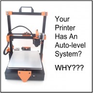
    I'm not convinced. Does anyone have pictures showing the difference in print quality between a regular auto-level system and this system?
     
  16. Keith Davis

    Keith Davis Veteran
    Builder

    Joined:
    Dec 11, 2013
    Messages:
    507
    Likes Received:
    398
    There are two levels to consider. The first layer level and the rest of the layers.

    If the first layer of both machines are indeed level and are otherwise outfitted the same, then there can be no difference in quality on the first layer.The difference there is in how level is achieved.

    But, with an auto-level system, disable the system after printing the first object. Then try print the same object a second time. Guess what, your first layer will not be level and you will need to enable the auto-level system to get it that way. The exact amount of change that the auto-level system has to make to get level again is just how unlevel the last layer of the first object was. That is because an auto-level system does not correct what causes a printer to get unlevel, it merely levels the first layer. The cause (the fact that two steppers can not be kept in sync) remains unchanged. Using only one motor syncing two Z screws with a timing belt eliminates that cause, guaranteeing that all layers will remain level, for thousands of print jobs. In a post on Twitter Joseph Prusa agreed with that basic fact, but maintained that his 9 point auto-system was "good enough" for consumer usage. And considering that the MK2 uses an easily warped PCB heat bed mounted to a design which is inherently almost impossible to get and keep "level", he's right, it's "good enough".
     
  17. Hellmut1956

    Builder

    Joined:
    Jan 17, 2021
    Messages:
    2
    Likes Received:
    0
    I am searching for a diy milling machine that uses SilentStepSticks. Those boards are well known from 3D printers. I am planning to use in a diy milling machine SilentStepSticksTMC5160hv. This stepper motors driver board can handle up to 60 VDC and I am planning to use a Meanwell 600W 48 VDC power supply just to feed the stepper motors. The SilentstepSticks TMC5160hv can handle up to 60 VDC and 20 A. So torque and speedy execution would not be a problem. The problem for me is to find a diy cnc mill that uses those SilentStepSticks and has the controller board and the software to operate a cnc milling machine.
     
  18. JustinTime

    JustinTime Veteran
    Builder

    Joined:
    Dec 18, 2013
    Messages:
    784
    Likes Received:
    259
    I don't think those driver can handle 20A at 60VDC. That's 1200W! I think they are rated at 4.2A, if memory serves me, and even then a good heatsink is in order. We had a short discussion on it a short while ago.

    4.2A, at ~3V, is pretty much what most stepper motors use, more or less. My NEMA 23, at 267oz/in, are rated at 3A and my NEMA 34 at 4.2N/m are rated at 4.5A but do excellent with only 4.2A settings.
     
    Peter Van Der Walt likes this.
  19. Hellmut1956

    Builder

    Joined:
    Jan 17, 2021
    Messages:
    2
    Likes Received:
    0
    As you know, the datasheet of a semiconductor component follows strict rules. The limitations are less due to the component, but more of the PCB and the heat diffusion. I had done experiments with a stepper motor and the stepRocker module from Trinamic but not yet those under load conditions. The stepper motor was specified to have a nominal value of 3.6 VDC and a current of 2.8A.
    You are definitely right that the SilentStepperStick TMC5160hv needs a heatsink as they are being used with all SilentStepSticks used in 3D printers.

    I plan to use the SilentStepperStick TMC5160hv supplying it with a Meanwell 48 VDC and stepper motors with a nominal current value in the range of 4A for a CNC milling machine. The main reason for using the 48 VDC is to ensure enough torque is always available.

    What I am looking for is to find someone that understands Marlin 2.0 enough so that a controller board like the one I have purchased. the BTT-SKR-Pro V1.2 can be used to control a CNC milling machine.
     

Share This Page

  1. This site uses cookies to help personalise content, tailor your experience and to keep you logged in if you register.
    By continuing to use this site, you are consenting to our use of cookies.
    Dismiss Notice