Welcome to Our Community

Some features disabled for guests. Register Today.

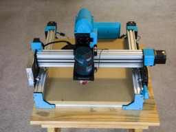
Sphinx 55 with 3D Printed Addons

Discussion in 'CNC Mills/Routers' started by David Bunch, Nov 28, 2018.

  1. David Bunch

    David Bunch Veteran
    Builder

    Joined:
    Oct 27, 2014
    Messages:
    624
    Likes Received:
    433
    I made my z-probe cable today & printed a Bosch Colt Dust Boot that I found on thingiverse. It has a couple of limitations for me that I mention in the comments on his page. The Z-Probe I made from 4 conductor wire I had left over from the MPCNC build & cut off the extra wires at the end. I attached the 2 leads as shown in the photo to (D3) & Ground connector. I was happy that I was able to connect them without taking board out of the case. I checked the continuity of the wires with ohm meter, but will wait for another day to test it. I laid a small wrench on the putty knife to keep it flat for the photo.
    IMG_6660_800x600.jpg IMG_6661_800x600.jpg IMG_6662_800x600.jpg
    The dust shoe I glued together with some Loctite super glue ultragel control which gives a little more time to set than regular super glue. Think I used up the rest of that glue on this part. I took the photo of dust boot on the router before gluing, so I put a couple things under it to hold it in place for the photo. That dust shoe also has a nozzle that threads underneath to give it a smaller opening, but it extends too far down on my router. The 2 different nozzles both threaded in nicely even though I am not able to use them. I am also not sure I can use the dust brush he shows. I will try this boot when I test drill all the holes on the spoiler board to see how well it works as it is. The tolerances on this assembly was very good as the parts went together nicely.
    IMG_6663_800x600.jpg IMG_6664_800x600.jpg
     
  2. David Bunch

    David Bunch Veteran
    Builder

    Joined:
    Oct 27, 2014
    Messages:
    624
    Likes Received:
    433
    The author of that dust boot design has a router is a little different than mine which was my problem.

    I tried the Z probe & timed out after hitting the metal. The video I have seen using this has those pins connected to two of the 10 pins on that connector just inside the board. Seems like I should be able to use the D3 & ground pin since it says the D3 is for Z-Probe. Is there another setting I need to make in the grbl firmware for this? I have not changed anything else in grbl since initially setting this up. I checked the continuity of those wires to the connector & they seem ok. Maybe I will post this the xPro thread also.
     
  3. David Bunch

    David Bunch Veteran
    Builder

    Joined:
    Oct 27, 2014
    Messages:
    624
    Likes Received:
    433
    I found the problem after a comment from the xPRO thread. There was a coating on the router bit that was not getting the connection. I also tested it on the A5 & GND connection that has been shown elsewhere & that worked also. Here is a photo showing the connection to the A5 (Orange Jumper) Gnd (Black) Jumper. While I had the case apart I added a fan guard on the inside since the 12v lead from the fan hit it once while I was making these adjustments. I attached that fan grill STL file here also.
    IMG_6666_800x600.jpg
    I am also playing with making that Dust boot one part & not using the sweeper at the bottom for now. Will test print it tomorrow to see what I need to adjust.
    BoschDustBoot.jpg
     

    Attached Files:

    #63 David Bunch, Mar 3, 2019
    Last edited: Mar 3, 2019
    GrayUK likes this.
  4. David Bunch

    David Bunch Veteran
    Builder

    Joined:
    Oct 27, 2014
    Messages:
    624
    Likes Received:
    433
    After watching the video with the link at the bottom I started thinking of a way to make something like this easily. My idea went from a little complicated 3d printed part to a simple part made from MDF. I found a large metal L bracket in my shed & will file down the inside corner fillet so it will be square against the corner. That will cut out the use of the metal tape on that part. I have seen other people use the metal stick on tape since it has virtually no thickness so I decided to make a simple mock up of this idea to see how it looks. I also made a simple 3d print design to see if that is worth looking at. One thing I also realized is the wall for the x,y stop can not be too tall as to hit the router collet Nut. Also the coating on some of my router bits might affect connecting the x & y. I can easily fix that by getting bits without that coating. The bit I am using at the moment is part of router bit set & not a true endmill, so I would probably be better off getting one of those anyway.
    IMG_6672_800x600.jpg IMG_6674_800x600.jpg XYZ_LPlate.jpg

     
  5. SugarJ

    SugarJ Well-Known
    Builder

    Joined:
    Nov 16, 2015
    Messages:
    126
    Likes Received:
    47
    Make your own touchplate out of aluminum, or 3D print and use your aluminum tape on the face and edges for connectivity. I've attached one I made on my machine out of 1/2" stock, feel free to modify and distribute.
     

    Attached Files:

  6. David Bunch

    David Bunch Veteran
    Builder

    Joined:
    Oct 27, 2014
    Messages:
    624
    Likes Received:
    433
    Thanks for the file. I will probably cut one of these eventually when I get around to cutting aluminum on this machine. Meanwhile I am playing with some other ideas.

    I got the basic dust boot working without the sweeper attachment & also has access to the collet nut that I could not get to with the original design. I took out the plastic level that protected the bottom of the router. I could see that would be useful when I start cutting aluminum, but will try this like it is for now to see how much MDF dust it picks up. I did crack the plastic around the base of the tightening bracket, so I might just make the gap go all the way thru as that probably won't affect the dust collection & I could always put a piece of scotch tape over it. It was also in the 20's in the shed when I tried that which probably contributed to it cracking. This PLA+ usually does not do that. I will include the STL file for this & the z-probe in case anyone wants to look at that design and I will publish the source files when I am happy with it.
    IMG_6683_800x600.jpg IMG_6685_800x600.jpg
    I also worked on a Z-probe mounting holder for a limit switch so I can I can use the auto level function in bCNC to create a z mapping of the surface. I want to do this before drilling all the T-nut holes on the bottom of the spoiler board. I was able to get bCNC installed on a Windows 7 machine after 3 attempts. I initially designed this limit switch holder in openscad, but this version I created in fusion 360 using parameter variables so I could change the design easily. I did not get the holder perpendicular to the bed at 1st & the yellow sharpie pen holder helped me to see that. I also put something 90 to it at the bottom to line it up. Since I am only holding this with one M5 screw on each side, it probably needs a longer tab on the top to hold it. I made this design 55mm from the bottom of the tool holder to the bottom of the bracket. That gives me about 10mm of height to play with. I am going to design an alternate version that uses something like the yellow holder you see in the photo & taper it down to hold the switch. That would be always line up perfectly perpendicular, but will probably be a longer print. I won't bother with the bracket gap in that since the front screws should tighten it down nicely. Also after looking at the video linked before, I started looking different kind of connectors to mount the gantry to have a quick disconnect for the Z-probe. The options I am considering are a 5.5 X 2.1mm Cable Plug Wire or an RCA jack cable. I am leaning towards the RCA plugs since I have some of these cables. I will probably need to get one 7'-10' to go to electronics case. Anyone have thoughts on this idea?
    IMG_6686_800x600.jpg IMG_6687_800x600.jpg
     

    Attached Files:

  7. SugarJ

    SugarJ Well-Known
    Builder

    Joined:
    Nov 16, 2015
    Messages:
    126
    Likes Received:
    47
    Thanks for posting that dust boot, I'll be printing one this weekend to try out.
     
  8. David Bunch

    David Bunch Veteran
    Builder

    Joined:
    Oct 27, 2014
    Messages:
    624
    Likes Received:
    433
    Since you are waiting until the weekend to print it, you will probably want to wait for this updated version. I will upload it if it works better. I am printing it now. Looks like it should have better air flow & hardly needed to add those 3 supports to the opening. I rounded the bottom under the vac duct rather than being more square & added some more support for the vac hose overhang. This is sized for a 1.25" vac hose, but with the openscad file that is easily changeable along with the offset from the center of the router. I tried to create this in fusion 360 also, but the lofting is not as easy as the hull() in openscad. This is probably mostly due to my current level of experience with fusion 360. I have about 8mm gap between the vac duct & the front of router mount. One thing I was thinking this morning was since I took that protective layer from under the router out of the original design, I could just print a press fit plastic washer to go under the router. Seems like that would be a good idea when cutting aluminum.
    BoschDustBoot_Rev28.jpg BoschDustBoot_Rev28a.jpg
     
  9. David Bunch

    David Bunch Veteran
    Builder

    Joined:
    Oct 27, 2014
    Messages:
    624
    Likes Received:
    433
    The dust boot looks pretty good on my machine, so I uploaded the design to thingiverse. Remix of Bosch Colt Dust Boot to make one part by GeoDave I also included a simple standoff washer to protect the bottom of the router, but not sure how well it will stay on there. I probably will not use that initially. I found a design of bosch colt router on grabcad that I used to match the holes & standoffs with.
    IMG_6698_800x600.jpg IMG_6689_800x600.jpg
     
    SugarJ likes this.
  10. David Bunch

    David Bunch Veteran
    Builder

    Joined:
    Oct 27, 2014
    Messages:
    624
    Likes Received:
    433
    I have been working on making a z-probe mount to fit where the router fits to do autoleveling across the whole bed with bCNC. If I understand this correctly, once it creates the z mapping, I would change to the router, set z0 & begin the cut. I used some speaker wire for this switch & routed it thru the drag chains. I use a 3'-1/8" brass rod to snake the wire thru easier along the straight run of the chain. I was all set to use RCA cables for this limit switch quick disconnect, but when I took one apart I realized it was like coax & did not really want to deal with that. I then had the bright idea to use USB cables, since I have a plethora of them, but different problem there as the wire is probably 28 gauge & seems to thin to mess with. My latest thought is to use the spade connectors like this fuseholder idea, but use 2 wires on each side instead of the fuse. I have a remix of this idea on my Delta printer & it works well with the fuse. Anyway for now I will just hang that wire on the side of the gantry when not is use until I decide what to do. I will use the other probe on the router for just setting starting Z0. I will post the STL file of that limit switch mount in case it is of use to anyone. I modeled this in Fusion 360 & switch button should be pretty close to the center. Since I cut off 2 sides of this round mount off to save print time, so you have to mount it front to back in the tool mount.
    IMG_6703_800x600.jpg IMG_6706_800x600.jpg IMG_6709_800x600.jpg
    I walked around Harborfreight today looking for ideas to use for a quick disconnect & discovered this 2.5" thick bone shape sponge for $2. Seems like this would work for a dust boot brush since it will compress to almost nothing and I only need to use half of the sponge. Just have to cut a hole for the router bit & glue it to a flat plastic mount. Since this sponge would be in the way of changing the router bit without taking this off, I want to make a magnetic disconnect mount for this like I have seen others use. It might not actually be in the way since it compresses, but the magnets would probably be better to use. I have some 1/2"x3/16" magnets to see if it works, but think flatter magnets would be better. The thicker magnets would require me to make the 2 mating mounts thicker. I found 50 - 3/8"x1/6" N42 for $7.19 that seem like they would work. I will order those if this test feels pretty good.
    IMG_6713_800x600.jpg
     

    Attached Files:

  11. David Bunch

    David Bunch Veteran
    Builder

    Joined:
    Oct 27, 2014
    Messages:
    624
    Likes Received:
    433
    Test print with these magnets seems quite strong, so I figured out a way to incorporate these without buying the flat ones. I just put them outside diameter of the dust boot. Half the weight of the sponge is only .4oz & with the .9oz plate with magnets attached this is hardly any weight at all that 4 magnets should be able to handle. I might have to cut the height of the 2.5" tall sponge down a little. The total weight will probably only be 1oz after cutting the sponge down. Here is the design I have for this so far. I had 5 magnets initially, but the 5th one might hit the gantry. With only 1oz of weight, 4 should be plenty. I have an air gap between the 2 plates as I read someone did that to help with air flow. The only thing I can think that might be a problem is when the sponge smushes whether it will get in the way of the router bit. Probably will not know that until I try it.
    BoschDustBoot_Rev34.jpg
     
  12. David Bunch

    David Bunch Veteran
    Builder

    Joined:
    Oct 27, 2014
    Messages:
    624
    Likes Received:
    433
    Oops, I forgot to click the Post Reply on this message on Sunday.

    Not sure I will put this on a magnetic bottom plate as someone on the facebook group commented this could break away & go up into the drive train. There was someone in that group that was using a sponge for this setup, but he had it directly glued to his vac mount. I will try my vac attachment without this sponge or brush attachment to see how much dust it actually gets without anything else.

    I got the bCNC program to do a 6x6 autolevel across the margins of my t-nut drilling sequence & was quite happy that the probe map showed a maximum of .156mm difference for that whole area. Think I will just cut it like it is.

    I did cut the harborfreight sponge today using a box cutter knife & it was pretty ragged cut. A hot knife might cut this easier. I had an old grout sponge that cut quite well & they are really less expensive than the harborfreight sponge if you buy 3 of them. I will have to work out a safer method for attaching this before actually using it.

    I think I am finally ready to drill those t-nut holes.
    IMG_6717_800x600.jpg
     
  13. David Bunch

    David Bunch Veteran
    Builder

    Joined:
    Oct 27, 2014
    Messages:
    624
    Likes Received:
    433
    I got my matrix of holes drilled today after 3 runs. The 1st run lost its correct Z height early on in the cutting. Luckily it was 5mm or so too high & not too low, so I was able to rerun it with no problems. I split the drilling for the 2.3mm depth & 19mm depth as 2 separate runs after that. I used the openbuilds Control v1.0.147 & it that software did something odd to begin with. After I homed the x,y & Z, I jogged it down to a couple mm's above the waste board & did a:
    G38.2 Z-5 F10
    & it started going up instead of down. I closed & opened the software & tried it again & it worked correctly that time. It also did this one other time. After I got it zeroed the 2nd time the cutting went ok. Not sure whether it was the software, a USB connection problem or some other problem on my machine. I will probably switch to bCNC once I get familiar with that software.

    Here are some photos of my progress. Seems like the vac attachment caught most of the finer dust. I like the little piles of dust it left at each hole. There was not much dust outside the cutting area. I only drilled down 19mm instead of all the way thru the wasteboard since I did not want to cut into the bottom board. I just printed a drilling jig to drill the final 1-2mm out of the bottom of each hole.
    IMG_6720_800x600.jpg IMG_6723_800x600.jpg
    I made a plastic hanging hook for my z-probe wire until I figure out how to handle that wire. I probably need to cover those end connectors also while it is not in use. I made this in fusion 360. I am starting to like that software.
    IMG_6722_800x600.jpg
     
  14. David Bunch

    David Bunch Veteran
    Builder

    Joined:
    Oct 27, 2014
    Messages:
    624
    Likes Received:
    433
    Well the sponge was a bad idea. I did 2 tnut holes & the sponge explode. Luckily it did not hurt anything. Guess it did not have enough ventilation. I only had a 3mm gap between the sponge plate & dust boot. I probably should have also made some slits in the sponge, but I am not going to pursue that idea any further.
     
  15. Giarc

    Giarc OpenBuilds Team
    Staff Member Moderator Builder Resident Builder

    Joined:
    Jan 24, 2015
    Messages:
    3,016
    Likes Received:
    1,682
    I like a bike inner tube with lots of slits. Used ones with holes are sometimes free from a bike shop. At least that is where I got mine. I zip tie it around my dust shoe. It has been the best solution I have found for me thus far. It sucks down good to the work surface and chips stay contained. I would like to claim it as my original idea but I saw it here first in Skarab's OX Fixed Dust Shoe . In my opinion, it was a simple yet a brilliant concept. No need for different brush heights. I like how the shoe stays the same height and the router plunges up and down through it. I would have done the same, but I need to modify my Z actuator first.

    Here is a picture of my tire tube if interested. I made sure to mount it in such a what that when it gets squished down, the rubber still can't reach the bit. The lower printed part the belt is zip tied to has a groove around it the zip tie squeezes into.
    DSC_0038.JPG
     
    #75 Giarc, Mar 12, 2019
    Last edited: Mar 13, 2019
  16. David Bunch

    David Bunch Veteran
    Builder

    Joined:
    Oct 27, 2014
    Messages:
    624
    Likes Received:
    433
    Thanks for the idea. We have 3 bike shops in our small city of less than 8,000 people, so I could probably get a used tube easy enough. I like the zip tied idea & will redesign this dust boot to add a groove to use for that & experiment with other materials. I will test it without turning the router on to begin with this time. I am looking at several materials, like bubble wrap with the small bubbles & cut slits along the edge like you did on the tube. I would like to use some sort of thick plastic, but not too thick. I did one using packing tape doubled over on itself for my MPCNC a while back & seemed like it helped some, but did not get all the dust. I want to get the dust under control before trying aluminum. I was originally intending to make an enclosure for this, but hoping I will find an adequate solution with just the dust boot. A ziplock back wrapped around might also work or maybe a towel cut to size.

    I just looked at the video in the link you sent me. That does look like it works well. Maybe I will have to look into that idea.

    I did get all my t-nuts put in place yesterday & working on clamping setup now. I took this Customizable 3" base Tensioner remix I did a while back & re did it in fusion 360 to match the 2" spacing I am using. Doing some test prints for hole & nut sizing before printing the part.
     
    #76 David Bunch, Mar 13, 2019
    Last edited: Mar 13, 2019
  17. Giarc

    Giarc OpenBuilds Team
    Staff Member Moderator Builder Resident Builder

    Joined:
    Jan 24, 2015
    Messages:
    3,016
    Likes Received:
    1,682
    You probably do not need to redesign it too much. I printed out a new bottom plate with the ring and glued it on with Tap Plastics acrylic cement which I use to chemically weld PLA. I did not want to reprint a part that took several hours to print the first time. It works just like acetone and ABS, but you have to hold the two pieces together a little bit longer.
    upload_2019-3-13_19-53-7.png
    Here is a very short (59 sec) video I made a bit ago from some video I shot a while back when making a cabinet for tool trays to slide in and out. I cut deep slots with a 1/4' end mill and the shoe sucked up almost all of it. You can see some of the more elusive chips escape every once in awhile.
     
  18. David Bunch

    David Bunch Veteran
    Builder

    Joined:
    Oct 27, 2014
    Messages:
    624
    Likes Received:
    433
    Looks like I would have to mount that dust boot bracket on the sides of C-Beam since there is not a place to mount it on the X-carriage in this design. I might be able to mount it to the bottom of the C-Beam end plate using those 4 screws, but that might be pushing the cantilever. I will have to make it extend out further than the original design unless I mounted the Vac to one side. From the Sphinx 55 sketchup files, the router is 69.6mm from the z Lead Screw & my Vac attachment is 72.45mm beyond that. I will work on this design some & see what I can come up with.

    Here are my progress photos. A ball peen hammer worked the best to make sure those T-nuts were in snug. That is the 1st time I really had a use for the rounded part of that hammer. The Hold Down Clamp Reinforcement I used as a starting point for making those corner clamps & redrew them in fusion 360. I like the edge tensioner clamps as they keep the work above the waste board, so that board should last longer. They worked really well on my MPCNC machine. The horizontal tensioner screws are a little difficult to get to with a regular screwdriver. Allen head screws might be a better choice for those. I added the last photo so you can see these clamps by themselves do not keep the work even across the bed which is why I added the corner clamps to hold them down. After putting these corner clamps on, I decided to make a couple of 10-20mm shorter versions so they did not extend into the work area so much. I included the STL files for these clamps here. The screws I used were 2-1/4"x1" for the tensioner clamps to connect to T-nuts, 2-#10x3/4" screws with nuts for the horizontal tensioner & a 1/4"x2.5" screw for each corner clamp. I added 2mm to the height of the clamp cylinder than was on original design so the 2.5" length screws did not bottom out.

    Edit: I deleted those corner clamps that clamp from the top. They were too tall to miss the gantry. I will have to make a shorter one.
    IMG_6732_800x600.jpg IMG_6737_800x600.jpg IMG_6736_800x600.jpg
     

    Attached Files:

    #78 David Bunch, Mar 14, 2019
    Last edited: Mar 14, 2019
  19. David Bunch

    David Bunch Veteran
    Builder

    Joined:
    Oct 27, 2014
    Messages:
    624
    Likes Received:
    433
    This CNC Hold-Down Clamp gives me enough clearance & I have used this one before. I redrew it in Fusion to take out some of the sharp edges. Think this will take a 1/4"- 1.5" to 1.75" screw. Probably can not get a 1/4-1.75" screw locally though. I also attached the STL file for this.
    LowProfileClamp_F3d.jpg
     

    Attached Files:

    Giarc likes this.
  20. David Bunch

    David Bunch Veteran
    Builder

    Joined:
    Oct 27, 2014
    Messages:
    624
    Likes Received:
    433
    I played with that design to connect to the Z-axis C-Beam & it just seems like too much trouble to do that. I was going to 3d print it rather than use acrylic. I went back to my other idea & put a groove around the outside to attach a wire tie for whatever skirt I put on there. The perimeter around that measures around 14", so I am going to use 2-11" wire ties together. I have some 18" wire ties, but they are around 9.4mm wide. The 11" ties are only 5mm. I left a wall between the vac hole & router hole to direct the dust more toward the vac opening & protect the router more. Seems like that is a good idea. Here is what it looks like so far. I will ponder this idea a little more before I print it.
    BoschDustBoot_Rev42_Section.jpg BoschDustBoot_Rev42.jpg
     
  21. David Bunch

    David Bunch Veteran
    Builder

    Joined:
    Oct 27, 2014
    Messages:
    624
    Likes Received:
    433
    I modified this dust boot design some to use less plastic & printing it in clear PETG from zyltech. Looks like a 4+ hour print. Here are some ideas I have for the boot skirt, bubble wrap, screen protector packing material(front of photo) & an old shower curtain. After looking at the Clear Acrylic Dust Shoe build log, I found this vinyl fabric I might try next time I am near a Joann's if one of these other choices does not work.
    IMG_6738_800x600.jpg
     
  22. David Bunch

    David Bunch Veteran
    Builder

    Joined:
    Oct 27, 2014
    Messages:
    624
    Likes Received:
    433
    I got a lot accomplished today. I redid the Reduction cover to just cover the front part since I find the need to turn that belt manually from time to time while adjusting this or that.
    IMG_6741_800x600.jpg
    I also adjusted the motor covers to have the Sphinx logo on 3 sides. There is also a honeycomb & OB1 logo design embossed on the 3 sides on the Openbuilds End Motor Mount Cover by GeoDave design page. I redid the motor covers in fusion 360 which made it easier to add those logos on all sides. I also made it a little thinner than the original design & print them with 0% infill. That makes them more pliable & they do not need any strength to them anyway.
    IMG_6740_800x600.jpg
    I got my dust boot reprinted with the changes today. It only took 3:44 to print it at 30%, 4 Perimeters & .28mm Layer height. I can now see why that rubber inner tube works well. I tested the suction with this packing material & it will suck the ends right in since it is not real stiff. I cut those a lot shorter so they can not get pulled in & will try a test cut tomorrow to see how well it works. I might go to Joanne's tomorrow to see how the clear vinyl looks & feels. I like the clearness of that rather than the rubber inner tube. I will attach the STL files of this new dust boot & the Vac support here if anyone wants to try it, since I did not put it on the thingiverse page yet.
    IMG_6746_800x600.jpg IMG_6748_800x600.jpg BoschDustBoot_Rev48.jpg
     

    Attached Files:

    GrayUK likes this.
  23. Giarc

    Giarc OpenBuilds Team
    Staff Member Moderator Builder Resident Builder

    Joined:
    Jan 24, 2015
    Messages:
    3,016
    Likes Received:
    1,682
    I tried clear vinyl and did not like it. I can't remember why. I think it got sucked in towards the vacuum all the time. It was leftovers from replacing windows in a vehicle I had which had a soft top. Mine may have been too tall, therefore making it easier to suck in towards the endmill. I just recall not liking the whole dust shoe I had made on which I used the vinyl. So, it may have been the totality of the circumstances and not just the vinyl. It was my first attempt at a dust shoe. I like the current one I have, but I don't love it. I will never be happy until I find a way on my machine to make it so the shoe is at a constant height and the router goes up and down independently. I would carry over the rubber inner tube though. That part is the part I have been happiest with. Look at me... I sound like I am sponsored by "The Big Popped Bike Tube Corporation." ;)

    One thing I may have forgot to mention: I did not split the bike tube by slicing it. I just cut the length I needed and fastened it so it is two layers thick which makes it stiffer yet still flexible.
     
  24. David Bunch

    David Bunch Veteran
    Builder

    Joined:
    Oct 27, 2014
    Messages:
    624
    Likes Received:
    433
    That tire tube does seem to be the best choice, not sure why I am hesitant to use it, maybe it is the smell of rubber. I really do like the idea of the stable boot connection versus moving with the router & after reading your comment early this morning, I realized I could add a side bracket to the C-beam on each side & not loose much if any X-axis space. 4mm should be thick enough for that. Here is my basic idea so far. I want to add a groove for the skirt like I did on the other design. I was originally looking at using those front 2 screw holes & 2 of the bottom c-beam screws, but it looked like way too much overhang. This design solves that problem. It is still a bit long at 207mm, but not too long for my printer. I printed a short plate just covering the router hole & only connecting to the front bottom just to see how it looks on the machine. I do have too much overhang on the cutout on the side brackets & will fix that before test printing.
    Stable_DustBoot.jpg
     
  25. David Bunch

    David Bunch Veteran
    Builder

    Joined:
    Oct 27, 2014
    Messages:
    624
    Likes Received:
    433
    I worked on this some more today & looks like it has a good chance of working. Big question will be whether it will sag too much or not. I did the test print at 1mm thick. This is at 4mm thick & when the 13mm high skirt plate is attached with M3 screws that should stiffen it up even more. Also looks like I will loose 4mm on each side of the x-axis where the side brackets attach to the C-Beam. I made the side brackets 4mm thick also, but recessed the screw head 2mm. Here are a couple of photos & screen shot of current version. From the 2nd photo looks like the top of the collet nut will be about at the top of the dust shoe plate when it bottoms out for me. I also picked up some 16 gauge clear vinyl today to try. I will also have to make top mount for holding the vac tube as the other one I made was on the moving part of the Z-axis. I just looked at this again & realized I only have 30mm of space below that C-Beam End plate before adding anything to it. I had realized that before, but had forgotten about it. If I only had 1 sheet of MDF on there, I would have an extra 19mm of clearance. Will have to ponder it further.
    IMG_6749_800x600.jpg IMG_6750_800x600.jpg StableDustBoot_WithSkirt.jpg
     
    #85 David Bunch, Mar 17, 2019
    Last edited: Mar 17, 2019
  26. David Bunch

    David Bunch Veteran
    Builder

    Joined:
    Oct 27, 2014
    Messages:
    624
    Likes Received:
    433
    I finally decided on banana plugs for the quick disconnect on my Z-probes. I had to attach the 18gauge speaker wire to the outside of the male connector, since the screw would not clamp on it in the inside. Guess these plugs were made for bigger wire. I like the way the mount came out & hidden behind the back of Z-axis C-Beam. Here are some photos & the attached STL files for the mount. I added a couple of holes for a zip tie in the bottom part, but didn't use them. The zip tie would have gone across the soldered part & seemed tight enough without it.
    IMG_6751_800x600.jpg IMG_6753_800x600.jpg IMG_6754_800x600.jpg IMG_6755_800x600.jpg IMG_6756_800x600.jpg IMG_6757_800x600.jpg IMG_6758_800x600.jpg
     

    Attached Files:

    GrayUK and Award like this.
  27. Award

    Award Well-Known
    Builder

    Joined:
    Nov 12, 2018
    Messages:
    60
    Likes Received:
    35
    The quick disconnect for the probe is a great idea - I've been wondering how to do it and you've come up with a really neat solution.

    Cheers

    Adam
     
  28. David Bunch

    David Bunch Veteran
    Builder

    Joined:
    Oct 27, 2014
    Messages:
    624
    Likes Received:
    433
    Thanks. After thinking about it last night, I am going to tweak the design a little and add a narrower tunnel at the back end of the mount to better keep debris out. Since it is behind the Z-axis, should not be much of a problem, but should be easy enough to add some more protection. Here is what I came up with. I added a 12mm long tunnel with a 5mm OD hole to a 5x10mm Ellipse. Going to run a print of it now.
    BananaPlugFemaleMountF3d.jpg
     
    #88 David Bunch, Mar 21, 2019
    Last edited: Mar 21, 2019
  29. David Bunch

    David Bunch Veteran
    Builder

    Joined:
    Oct 27, 2014
    Messages:
    624
    Likes Received:
    433
    I finalized this design & uploaded it to thingiverse. The last change I made was to make that tunnel a slot opening since I had already soldered that wire & the soldered part would not fit thru that hole. I used a bigger clip on one of my leads so I could clamp it to the collet nut on the router instead of the bit since that is a better electrical connections than some of my bits that have coatings on them. The alligator clips I got from harbor freight.
    Banana Plug Quck Disconnect V-Slot Mount for Z-Probe by GeoDave
    IMG_6771_800x600.jpg IMG_6770_800x600.jpg BananaPlugFemaleMount_V3_F3d.jpg
     
    Award likes this.
  30. David Bunch

    David Bunch Veteran
    Builder

    Joined:
    Oct 27, 2014
    Messages:
    624
    Likes Received:
    433
    I have worked out all my current problems except my dust collection scheme. This dust collection method probably picks up 50% of the dust. I did my 1st real cutting today with this 4" round Yin Yang symbol with cats. It came out as expected. Probably took about an hour to cut. I should have added a chamfer cut around the top edge so I do not have to sand that. I used an 1/8" bullnose endmill I bought 3 years ago from Drill Bits Unlimited | eBay Stores & ran this in 2 separate cuts, the carve cut & the parting cut. I used Estcam to create the gcode. The parting cut I had 4 holding tabs 3mm wide by 3mm high. I used .5mm cut depth for 2 passes on the carving & 15mm/s feedrate. I forgot what kind of wood this was, but I bought it from Cormark International which is less than hour drive from here. I also used some left over bamboo flooring pieces under my wood so it would cut into them instead of the MDF board I spent so much time creating. That worked out well. I still have not resurfaced the spoiler board, but it seemed level enough for this cut. I did some video of this cutting & if it came out ok, will post that in a later message.
    IMG_4003_800x600.jpg IMG_4006_800x600.jpg IMG_4009_800x600.jpg IMG_4011_800x600.jpg IMG_6775_800x600.jpg
     

Share This Page

  1. This site uses cookies to help personalise content, tailor your experience and to keep you logged in if you register.
    By continuing to use this site, you are consenting to our use of cookies.
    Dismiss Notice